noughtnaut
-
Still alive (just being an idiot)
07/06/2023 at 21:52 • 0 commentsHiya.
This goes out to all nine of you who are following my project. I'm terribly sorry for the lack of updates, which accurately reflects the lack of progress. Real life sort of gets in the way, you know how it is.
However, one notable thing happned: it occurred to me that I'm an idiot. Yeah, no, to be honest I kind of knew that already, but I've found a new way of being one. See, I swear had I the Accom keyboard working perfectly, and I had the VFD working perfectly, too. Put them together, and havoc ensued. Courtesy of a shower thought, I'm pretty sure I now know why that is, and two plans of moving forward.

'member me? I'm the main board. 
Lookit teh shinies! 
"Look! Look! Look where I'm pointing!" 
slightly broken, and also wrong The keyboard, using the ribbon cable, passes active-low signals back to the main board. The main board also holds the 18 lighted key switches, which don't go through the ribbon but directly to a bank of PAL chips (which I've lifted out in order to tie in a separate 34-pin ribbon that goes to the other box socket on my fancy red PCB).
...only, the signals to the PAL chips are active high. 🤦
I know, right? Since I'd drawn up this fancy red PCB with the dual 34-pin box sockets, apparently it never occurred to me that the signals might be incompatible. So, now, I'm thinking: do I redesign my board and "spend more pins" on separating the bus into two; do I create a little daughter board to invert the signals; or do I attempt to program the Teensy to switch pin modes from active low to active high smack in the middle of each scan?
Currently, I'm considering buying set of male/female 34-pin connectors and a couple of TI 74HCT14N logic inverters, and build a small daughter board. I don't think I want the mess of mode switching in my source code, and I definitely don't want to allocate more I/O pins as I'm not sure I even have enough to fully support the 7 rotary dials and the track ball. This final issue might have been less critical if I hadn't destroyed the solder pads of a bunch of the I/O's on the underside of the Teensy ... or if new Teensies were expected to be back in stock sooner than 10 months from now. Talk about long-term lingering effects from the Covid pandemic.
-
Completing the migration to PlatformIO
02/12/2023 at 22:01 • 0 comments# Underside Teensy solder pad "pins" are fragile
I've struggled a ton with understanding why my keyboard was acting up: some keys were unresponsive, and some reported keypresses for themselves and other keys. Turns out, it's a hardware issue, and the "active low" logic had me all confounded.
By profession I'm a programmer not an electronics engineer, so it wasn't easy for me to get all those solder pad "pins" on the underside of the Teensy connected. I'd used a standard dual-row header where I'd bent the top of the pins 90* outwards, but it turned out to be super fiddly to get them all aligned and I managed to destroy two of the pads. Well, I've apparently managed to destroy some more: I've got a big desk but a huge console and so I shuffle things around a lot, and apparently out of the pins numbered 40-53 it's not just 41 and 42 that were broken, but (now) also 40 and 51 which I use for addressing the keyboard. In figuring out replacement pins, I discovered that pins 43-48 don't work either -- so out of the 18 solder pad "pins" I only have six remaining that actually work, two of which are still unused. This leaves me with a total of 11 unused pins; I hope that's enough for the trackball and the seven rotary encoders...
# Keyboard driver revamp hurdles
As mentioned in my previous log entry, now that I'm using CLion I've returned to the PlatformIO framework. This combination provides me with a pleasantly integrated development experience.
As planned, I'm now reworking the keyboard driver, but it's giving me some grief. The PlatformIO project is configured for a Teensy 3.5, but the Keyboard.h file (provided in ~/.platformio/packages/framework-arduinoteensy/cores/teensy3/) contains a comment literally saying it's an "empty Keyboard.h file". I suppose this is a configuration issue and that there is a way to make the compiler (and IDE) understand to use the stock Arduino header file.
I've asked the oracle yet again, but so far no guidance.
-
Sponsored C++ IDE
02/10/2023 at 08:31 • 0 comments# I used to think that I was indecisive; now I'm not so sure ...
I've been vacillating between programming environments.
- I obviously started out with the Arduino IDE which, while capable enough, isn't as helpful as I've come to expect from other IDEs.
- So I switched to IntelliJ. "Wait, Arduino code is C++ and IntelliJ isn't that" I hear you say, and that's correct, but for a hobby project CLion is sorta expensive and so I chose a JetBrains product with a free Community Edition.
- I couldn't get the Serial Monitor to work right, so I still kept the Arduino IDE open just to make use of its serial monitor.
- With IntelliJ, there's a neat plugin for PlatformIO which I tried out (rewriting what code I had at the time), but I had hang-ups with integration so I went back to a plain Arduino-style project while continuing with IntelliJ.
- Even though the IntelliJ editor is much nicer than the Arduino IDE, given that it's just not designed to be C-aware I didn't get much help. But I've been using this approach for a good while now.
Then it occurred to me that JetBrains offer free licenses for open source projects! So I applied, and demonstrated that this is, in fact, an unpaid open source project -- and they have awarded me a one-year license to ALL their products! They didn't ask me to review or mention this in my project, but here it is all the same.
- Now I'm able to use their dedicated C++ IDE, CLion!
- CLion doesn't know Arduino, so I needed to rework my "ino" file into a C file. No biggie.
- I'm also revisiting the PlatformIO framework, as it seems better integrated with the IDE but requires a different approach to organising files (more rework).
- I still haven't been able to get the Serial Monitor to work, so for now I will stick to my acceptable work-around of using the serial monitor fromthe Arduino IDE. It's a minor annoyance; I may look into it again later.
# So how is the project doing now?
Ahh, it is such a pleasure to be able to refactor ruthlessly and confidently. I have reworked the code for the PlatformIO framework and now the display driver is rock solid and super fast despite using a serial connection. I've yet to rework the keyboard driver, but that will follow soon.
As usual, the code is on GitHub.
-
New board in action
01/15/2023 at 23:33 • 0 comments# Board migration
Ugh, getting my Teensy off of the perfboard was a mess. I didn't have any headers on hand so I had simply soldered the microcontroller board directly to the perfboard. I tried snipping all of the pins near the perfboard but I obviously couldn't get to the ones down the middle of the Teensy, so I ended up taking a miniature angle grinder to the perfboard. Copper and fibreglass dust galore! Ugh. Lesson learned.
On the new pcb, I've installed proper headers so that I can (theoretically) pull the Teensy out again, and I also transplanted the two 34-pin box headers. Using a temporary mount, I've placed the board within the console enclosure along with the dual-voltage power supply I had hacked together earlier.
In the process of designing an orderly layout for the pcb, I had reassigned a couple of the Teensy pins. I've also reassigned the corresponding constants in my Teensy code, so it "should" work. 😀🤞
Except of course, it doesn't. 😖
The keyboard is all screwed up; parts of the keyboard (corresponding to distinct demultiplexers) are completely nonresponsive, while others report many, many simultaneous keypresses. Also, for some reason, the VFD is no longer working consistently; posting a stream of identical characters shows a few percent of seemingly random deviations (either other characters are printed, or there are changes in brightness, cursor style, or other behaviour normally caused by some of the special byte values). This indicates either line noise or poor signal timing, but I am doubtful that the new signal path has introduced line noise and the signal timing hasn't changed so I am somewhat confounded.
But then again, it's hella late so I shall proceed by sleeping on it.
...
# Keyboard bliss
Mystery partially resolved: It seems two signals didn't make it from the Teensy to the ribbon cable socket. I don't blame the pcb manufacturer for this; I must've damaged the solder pads on the back of the Teensy where the signals originate. No big problem though, this is one reason why I wanted every trace on the board to have at least one additional pad: so that I could simply remap the signals from those pads to proper pins and install two patch wires from the new Teensy pins to the ribbon connector. Ta dah, now the full keyboard works beautifully (except, of course, that as a keyboard it's really not all that great to type on 🤭).

pcb with patch wires # VFD parallel data woes
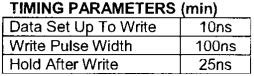
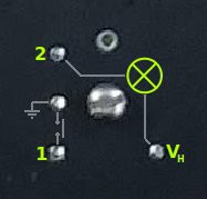
So that resolves the keyboard. But what of the VFD? The switch to high-speed parallel implies setting the data bits and then (momentarily) setting WR active ... but whenever WR is set LOW, the display goes into a flickering state as if it's being continuously reset (as opposed to only once when receiving a Reset signal). This does not seem to be in line with the datasheet:
 signal according to data sheet for NEC FC20X1SA 1x20 VFD")
A(0) signal according to data sheet for NEC FC20X1SA 1x20 VFD 
FC20X1SA timing diagram Alas, the 1-page data sheet for the NEC FC20X2JA (with 2x20 characters) merely mentions "many control commands are available" but does not provide further details. It does say this about timing, though:
![]()
Since the Arduino platform and the Teensy 3.5 doesn't provide nanosecond precision, I'm just going to wait a microsecond for each of those.
Alas, I have tried a zillion different approaches including asking the hivemind, but no matter what I do, setting WR active seems to perform a reset instead of a byte read. 🫤 I have yet to find a way around this.
Any ideas?
-
Sponsored PCB manufacturing
12/29/2022 at 12:21 • 0 commentsI haven't mentioned this earlier because I didn't feel I was ready to make use of it, but I was contacted by a company named PCBWay with an offer of free pcb manufacturing for this project.
In an earlier project log I showed how I'd rigged up a Raspberry Pi to the keyboard ribbon by way of a breadboard. I had fiddled a bit with a little pcb design, but knew from the start that it wasn't going to be in the final product so I didn't really intend to have it manufactured.
Now, though, I'm further along, having upgraded to using a Teensy microcontroller on a perf-board. But the fact that I simply plunked down the components pretty much anywhere has now come around to bite me: the perf-board is getting too crowded to implement the remaining interfaces (lights and dials).
To expand to the full capabilities, I need to clean this up. And what better way than to take the opportunity to make a nice, real, pcb? I've tinkered with a design that meets a few criteria:
- large enough to make ends meet, physically, wrt. the ribbon cables
- small enough to fit comfortably in the enclosure (still need to double-check how much room there are for headers)
- neat and logical double-sided routing
- prepared for future expansion and re-work
With this in mind, here's what I've come up with:

PCB render, courtesy of EasyEDA 
Diagram of Teensy and two ribbon sockets The ribbon sockets are far enough apart to make ends meet while keeping the board footprint small. The space in between is used for signal routing. Importantly, every single pin has a separate solder pad. This means I can patch in additions later on, and even repurpose the board entirely if I need to (possibly by cutting a few traces).
PCBWay does a minimum of 5 boards per order, so I can populate one with nice headers everywhere to finish up my prototyping work, and then use another to make a tidy final version. I'm submitting my order today, and am excited about when I'll get a package in return! 🤞🙂
----------
You know the feeling, right? You've ordered something online, and the minute you click "Confirm" you're antsily waiting by the door for the postman to arrive. That, at least, is me.
I am rather impressed by the detailed progress tracking PCBWay make available through their web site. Each of those items are clickable and take you to a video walkthrough of that particular manufacturing step. Taken together, it's pretty much a rather educational "How It's Made" episode.

Detailed progress tracking I placed this order on the 30th of December. It's now January 9th, and I just had a visit from the postman!

FedEx bag, box, foam, bubble wrap, shrink wrap The five boards were shrinkwrapped onto a sheet of bubble wrap, which I've never seen before. I can't wait to transplant my Teensy onto this shiny thing!
-
Main system board: sensing key presses
12/14/2022 at 13:40 • 0 commentsIt's time to implement keypress detection for the 18 lighted switches. The two demultiplexers "M" and "N" share a number of their inputs; "DMX SEL" (pins 1, 2, and 3), as well as "G2B" (pin 5) and "G1" (pin 6). Again, both these demultiplexers are socketed, allowing me easy access to tap into their pins. However, "G2A" (pin 4) are addressed separately; and the respective outputs go to the "output enable" pins ("G1" and "G2", pins 1 and 19) on the bulb control chips "D", "E", and "F" (for "M") and the key sensors "J", "K", and "L" (for "N").

Main system board, labelled As stated previously, I'll need to provide DMX SEL signals for the LS138 "N", and read out signals on pins 12-19 of one of the PALCE chips ("T", "V", "X", and "Z" -- they're all connected in parallel). I'm going to solder leads from the ribbon cable to a chip header which I can then drop into one of the sockets on the board.

Main board return lines On the Teensy side, I can re-use the same pins for the "DMX SEL" and return signals as for the rest of the keyboard interface, and I'll dedicate two pins for "G2A" signals. Oddly, the long green patch wire connects "B Select" from "M"/"N" to pin 31 on the VFD daughter board; this is not used by the VFD, so what is its purpose?

Relationship between keys, PALCE's, and bulbs For example, pressing [VFD Menu 1] (key #13) signals pin 11 on "K", which will output a signal on pin 9 to pin 16 on one of the PALCE chips (as well as pin 4 on "S" but we don't care about that just yet). However, that is only the case when the "Output Enable" (pin 1+19) on "K" is active, which is controlled by pin 14 on "N" by setting its G2A low, and configuring its "DMX SEL" to "H/L/L".
I've expanded my existing kepboard driver to include the "G2A" pin of demultiplexer "N" to scan the lighted keys. The "DMX SEL" signals are used differently than for the other keyboard parts; rather than using the entire binary sequence they are simply addressed one-by-one. Therefore, I've modified my driver's sequencing to not run through the full 0b000-0b111 sequence but only 0b000, 0b001, and 0b010, so that the scanner doesn't waste time checking dead leads. For code efficiency, on the "L" chip 6/8th of the return line scan will be superfluous, but in terms of response time that's (hopefully 🤞) negligible.
I've yet to do the solder work to see if it works as intended (ominous foreshadowing).
(This did, in fact, turn out to not work, as I'd somehow ignored that the keyboard uses active-low signalling, but the main board switches use active-high signalling, thus borking decoding entirely.)
-
Main system board
11/25/2022 at 14:09 • 0 comments# Main system board (log resumed from 2022-09-08)
(Yes, this keeps getting pushed further into the future. Soon I will have nothing else left to work with though, and eventually will "have" to get this one done.)
This board holds 18 lighted keys and 6 dial knobs. Shown here without the VFD daughter board.

Main board, front 
Main board, back What I initially thought of as the "VFD section" is really the main board, as it includes the CPU, firmware, communication, sockets for the trackball and jog wheel, and power input. There's also an intriguing little 4-gang piano on the underside; I wonder what it does?
There are so many ICs on this board, I'm going to label them:
![]()
## Power
Diving into the traces of the Molex power socket, it's clear (and unsurprising) that all of the logic runs on 5V. The incandescent bulbs in the 18 key switches are rated for a higher voltage and glow rather dimly if supplied with a measly 5V. Although the bulbs are rated for 14V I am still unsure what this "higher power" voltage is meant to be. I'm going with 12V until I find out otherwise.
Pin 4 of the Molex connector is wired to 3 places: pin 5 ("+V(s)") of the op-amp jutting out over the edge of the board in the top-left side; to the corresponding solder pad of an empty space that might be intended for another op-amp; and to a power choke (RL1283, labelled "L2", the other side of which eludes my tracing attempts).
The L165 power op-amp is connected thusly:
Pin Datasheet Actual connection 5 +V(s) Pin 4 (yellow): 12V ?? 4 Output GND (wtf really??) 3 -V(s) Pin 2 (black): GND 2 Inverting input ?? (not yet traced) 1 Non-inverting input ?? (not yet traced) I don't understand the L165 datasheet well enough to understand what the output on pin 4 is supposed to be. Should it be half-way between the voltages on pins 5 and 3 (so half the voltage on pin 5)?? Are pins 3 and 4 supposed to be tied together, and connect to ground (or is this component busted, or is this just he powered-off state)?? And are pins 1 and 2 important on this board??
Curiously, the final Molex signal (pin 3, white cable) seems to be connected to pin 3 (" -V(s)") of the omitted op-amp; and to another power choke (RL1283 again, labelled "L3"). It must be used for something, but what?? I'm assuming it's just a ground connection.
## Brains
As mentioned, there's a Zilog Z80 in there, alongside an AMD AM85C30 serial controller (these are the two square chips above the Molex socket on the left side of the board), and a bit to the right of them there's a 20MHz crystal. The large brown chip above the serial socket is an AMD AM27C256. Under the 12-button cluster, there's a flock of PALCE16V8H chips.
Close to the serial controller, there's a small (soldered-in) daughter board marked SHUTTLE ENCODER BD which may prove useful for, uh, decoding the jog wheel. That's for later, though.
To the centre-right (which would normally be underneath the VFD daughter board) are four SN74LS374N edge-triggered flip-flops, two (equivalent?) CD74ACT374E flip-flops, and three TI SN74LS244N line drivers. There are two DM7406N logic inverters between the 12-key cluster and the leftmost above-the-VFD key, plus (curiously) a third all the way down in the right-hand corner. Between the two leftmost dial knobs sits a single AD557 8-bit DAC.
### Firmware
For sure, the large brown AMD AM27C256, being a 256kb EPROM, must be the control panel's main firmware.
I am somewhat unsure, though, what the PAL chips represent; according to their datasheets, they are programmable but, as far as I understand, only once (as these do not have windows for UV blanking).
## Switches
I've had no luck finding datasheets for the LKS-2-A 9406 lighted buttons. It's not really important; they're just switches with incandescent bulbs in them, but they are oddly tall and have a sort of military or soviet look to them.

LKS-2 key switch These keys are not wired into the ribbon cable. A pity; that could have provided a nice single source for all button states.
![]()
LKS-2 key switch pin-out ### Sensing
The switched pins (pin 1) of all the keys are pulled high via a resistor ladder (right of "L"); closing the switch pulls their signal low. This output is fed into the SN74LS244 inverters ("J", "K", and ¼ of "L"), whose output enable pins are controlled by one of the multiplexers ("N") over near the jog wheel interface socket. The inverted output then goes to PAL chip ("T") and to the latching DAC ("S").
Meaning, whenever a key is pressed and the corresponding output enable pin is pulled low, the PAL chip gets a high signal on a partucular pin. Keys 1-8 correspond to pins 12-19 on "T" when pin 13 on "M" is high; keys 9-16 correspond to pins 12-19 on "T" when pin 14 on "M" is high; and keys 17 and 18 correspond to pins 12 and 13 on "T" when pin 15 on "M" is high.
What the output of the DAC is used for I've not yet investigated. Given that it's a latching DAC (and that the keys are sensed through multiplexed scanning), it's likely that the DAC serves to store which combination of the 18 keys are active (which will then be used for lighting them, as well as knowing which mode-specific VFD output to provide, and what control inputs are to be interpreted as).
Right now, I'm thinking that this is where I might "cut traces", so that the input/output components talk to my microcontroller instead of the PAL chips (and the rest of the CPU components). In reality, all the relevant chips (the PAL chips "T"-"Z" and the multiplexers "M" and "N") are socketed, so I can simply lift them out and re-use the sockets for prototype wiring. Brilliant. Thanks a lot, Accom!
// TODO Hook up the multiplexer ("N") and the PAL ("T") to my microcontroller and include them in the keyboard scan to read the state of these 18 lighted keys.
### Lighting
The switches contain AML7382 bulbs rated 14V 80mA; apparently, they're typically used in aircraft instruments (so illuminating all bulbs would draw just shy of 1.5 amps).
Lighting the bulbs seem to be controlled by the three DM7406N logic inverters ("A", "B", and "C"), which supply one output for each bulb (pin 2); the other pin of all bulbs connect to the outupt pin of the L165 power op-amp. The 6 inputs of each 7406 come from the 8 outputs of the SN74SL374N latching flip-flops ("D", "E", and "F"), thus utilising 2¼ of the 4 chips. Their inputs are wired in parallel (all pin 3 inputs together, all pin 4 inputs together, etc.), so this puts them in a matrix configuration if their CLK pins are individually addressed -- which indeed they are, from "M" pins 13-15.
Or, seen in the direction of information flow, the PAL chips send data to the AD557 DAC ("S") as well as the three SN74SL374N latching flip-flops ("D", "E", "F") whose outputs are sent through DM7406N inverters ("A", "B", "C") to the light bulbs.
// TODO Hook up the multiplexer ("M") to my microcontroller and see if we can command keys to light up.
### Summary
So far, I have cleared up usage of 6¼ of the 9 chips underneath the VFD, all of the other chips on that side of the board (except what the DAC is used for), and one half of one of the (at least) 7 PAL chips.
It seems that the PAL chips can be used as outputs as well as inputs; I'll have to investigate timing to see just how. But clearly, the same PAL chip pins are used both to read key presses, and to toggle lighting. This might just be clever enough so that pressing a key "automatically" also toggles lighting??
All in all, here is a wiring table of the 18 lighted keys on this board:
![]()
## Dial knobs
As for the dial knobs, they're HRPG-ASCA #19R 9323 rotary encoders which provide 120 pulses per revolution. The datasheet recommends combining each with a "HCTL-2016/2020 QUADRATURE DECODER/COUNTER", but here they are routed to the two ACT374E flip-flops ("H", "I") whose outputs are wired into the PAL chips.
// TODO I've yet to look into sensing these dial knobs.
# Current thougths
I would rather not comment on the amount of time finding this out has taken me. Ugh, I am all too aware of my poor understanding of electronics (I pretty much just follow traces and read datasheets) ... but I bet that even so I can make this work as envisioned.
-
VFD success ("good enough for now" milestone)
11/13/2022 at 14:52 • 0 comments# VFD daughter board
I probably don't need to investigate this too much as it is a stock component; a NEC FC40X2EA-AB with 2 lines of 40 characters and a serial interface. I just wanted to include the pics for you.


VFD daughter board, back I have not yet found the datasheet for this specific character display, but I have the ones for the related single-line 20-character (FC20X1SA) and 2x20-character (FC20X2JA) boards. I expect the control interface will be identical; the daughter board has a 9600 baud serial interface and a power supply socket. Apparently, the 1x20 VFD requires 4.75-5.25V and draws 700mA, which frankly is less than I expected -- just shows how little I really know.
## My implementation
I've grabbed another old floppy drive cable and picked it apart. For one thing, this allows me to prototype things with my existing board by using this cable in place of the one for the keyboard. For another, the display doesn't require so many leads, leaving plenty of capacity to be used for interfacing with the 18 lighted key switches, the six rotary encoders, and the trackball.
On the VFD daughter board, all of the even-numbered pins are connected, and so my ribbon only provides GND on pin 34. Since I am using the serial data connection, I also don't need the 8 pins for parallel data. Additionally, after using the "T(0)" test mode signal to verify that the display is, in fact, functional, I have no further use for it. Finally, the "CS" should always be set low (which makes me wonder why it's even there?) so it will be simply connected to GND on the VFD side. In total, I need 6 leads (and only 5 Teensy pins) to drive the VFD, leaving 28 leads free to be used later on.
I've spent some time experimenting with the protocol. There are still some odd bits where my code doesn't work even though I seem to have done everything to spec.
According to the datasheet, the 34-line ribbon cable is used as follows:
Ribbon line Signal 34 GND 17 WR, Write data to display (set high when sending commands, low when sending data) 19 A0, Activate input (set low while sending serial data, then set high) 23 Not connected: CS, Send command (should always be set low) 25 Not connected: T(0) (set high at power-on(!) to enable test mode) 27 Busy signal from VFD (unable to receive data when high) 29 BL (set low to blank display, high to unblank) 33 Rx, Serial data
Active high. Data packet is one start bit ("0"), then 8 data bits (LSB...MSB), then one stop bit ("1").It took me a while to figure out which signals were active high and which were active low, as this does not seem to agree with the datasheet. By the way, using the default 9600 baud setting means working with pulses of 105µs which the Teensy can easily churn out.
But hey, look at this beauty!

Sad attempt at embedded video I've implemented some simplistic code to "put this string of text at this position", along with commands to control the cursor style and display brightness. The "Slot #" sequence shows a weakness: my display refresh code is not fast enough to provide real-time feedback when adjusting a value (say, volume control) using a rotary dial. This is because I am still struggling with absolute positioning; there is some oddity between how the datasheet says to use the "WR" signal to send commands, and how it actually works on my unit ... so for now I have to use relative positioning, which means sending the full 80 characters regardless of how much I actually wanna change. What I'm saying is, I should be able to make this much faster (at least 10x, possibly 60x) when I figure out the "WR" signal.

VFD showing test message 
VFD showing menu slots In this last image, you get an idea how the original system used to operate: the top row would have menus such as "colour balance" or "timing", and pressing one of the white buttons above would then load that menu, for instance showing "Black Level", "While Level", "Red", "Green", "Blue" in the top line and their individual values in the bottom line -- which could then be adjusted with the dial knobs and committed with the black buttons below them (not shown here, as they're physically part of the jog wheel board).
Next up: sensing the rotary dials and lighted switches, and controlling their lights.
-
USB keyboard feature - proof of concept OK!
11/13/2022 at 13:02 • 0 comments# It's alive
After restructuring the firmware code to work with the Arduino IDE, the console now works as a USB keyboard for most standard keys; non-standard keys are reported as [TEXT] with press/release events. MuahahaHAHAAH! I can do this!
I've published the code to github. I haven't yet considered whether all the files (diagrams, etc.) should be there, too, so for now they're just here at Hackaday.
I have a few minor issues with the hardware keyboard being capped with a US layout, which is not what I'm using logically on my workstation, which is why a few keys are seemingly mapped incorrectly. Also, the Teensy keyboard library seems to be lacking an [Alt Gr] keycode, so for now I just have two [Alt] keys.
Next up (beyond mapping the row above the keyboard to be function keys) is either working on reading the trackball and jog wheel, or resuming my work on the main system board so that I might light up the VFD and those additional 18 keys.
-
USB keyboard feature so very nearly done
11/11/2022 at 14:59 • 0 comments# Keyboard
You know when you're 🤏 thiiis close to completing a feature, and then you hit that "one tiny snag"? Yeah, that.
I have all the keys mapped out and can accurately report key press/release events. However, I have 189 keys which is quite a bit more than a "standard USB keyboard", so my plan was to report the "standard" keys using a built-in library (including mapping [REV] and [FWD] to [CTRL] and [ALT], etc.), and have the remainder of the keys send text macros until I write a host-side serial driver to interpret them (for instance, [FILE MNGR] could map to [WIN]+E, but I don't want to be that specific at the firmware level).
Anyone who's tinkered with microcontrollers knows that the Arduino IDE has, uh, lots of potential. That is to say, it works but phooey is it cumbersome as an editor. So I'm doing my coding in IntelliJ (using the CLI version of the compiler and using the Teensy loader to connect to the hardware, and also still running the Arduino IDE solely for its simple serial monitor.
Alas! Going off piste frequently means hitting bumps, and one such is that the standard Arduino headers are not implicitly available. So I can have `#include <Keyboard.h>` and have everything building just fine up until the moment I try to call `Keyboard.press(keycode)`. And yes, I have of course set the device mode in the Arduino IDE as per instructions, but those instructions don't take nonconformity into account. I imagine I can simply `#include "path/to/Keyboard.h"`, but I haven't found that path yet.
# Open source
Not that there was ever any doubt, I just hadn't gotten around to it yet -- this project is naturally going to be open source. Insofar as it makes sense given that the intended hardware for it is both rare and expensive. As of this writing, the code resides at GitHub and is under a 3-clause BSD license.
To be continued...
Repurposing an Accom Axial Control Panel
Turning an obsolete video editor console into a mothership-sized keyboard + trackball + stream deck


 signal according to data sheet for NEC FC20X1SA 1x20 VFD")