I am a software developer, but a novice at electronics and today's tiny programmable devices such as the Raspberry Pi Pico. In 1990 I wrote a how-to book on distributed systems, featuring C programming, Oracle SQL databases, IBM PCs, and mini computers. In the main example in the book, humans play a simple game against the computer. The computer learns to play by saving each completed game in an Oracle SQL database, and querying for the statistically best move before each play - a simple form of machine learning. The computer gradually gets better over time. Each game lasts about a minute.
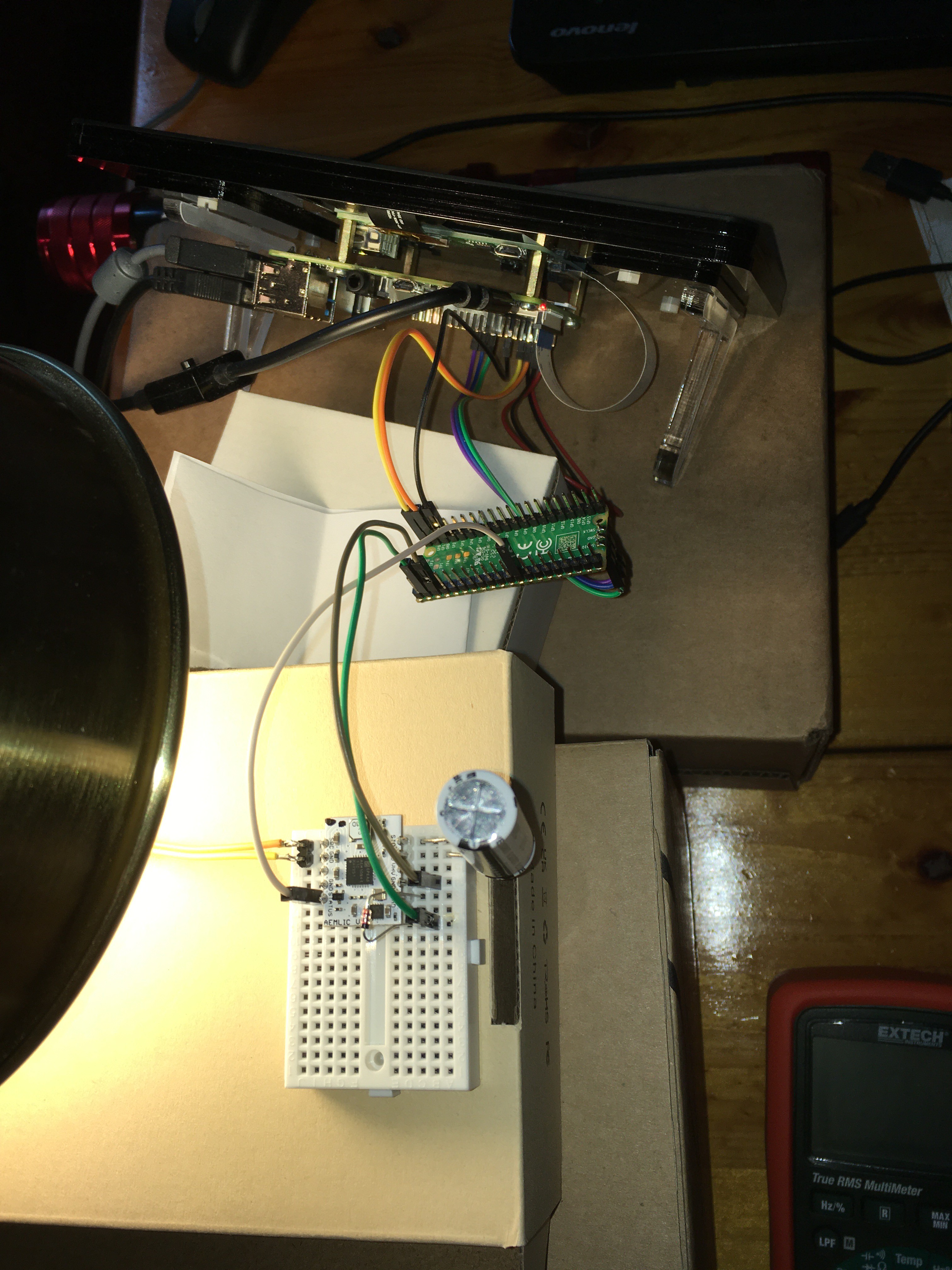
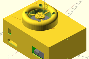
The original 1990 C code for the basic (non-database) version of the game compiles, with a few small modifications, on a Linux (or other) computer, and runs on a $4.00 21mm × 51mm Raspberry Pi Pico (https://www.raspberrypi.com/products/raspberry-pi-pico/). The UI, for initial prototyping, consists of a small joystick and a tiny OLED display. It's powered through a USB cable, or through a pair of wires from a larger Raspberry Pi 4.
For now, this is a concept project, and a good way for me to learn a bunch of things. My goal is to run the complete game on the Pico, using energy harvested from the local environment, for example through a low-power solar cell. As a concept, imagine the small Pico attached inconspicuously to a tree in the woods. Anyone finding it could spend a minute or so playing a game, thus adding to the internal database. The Pico would harvest just enough energy between games to power the next game.
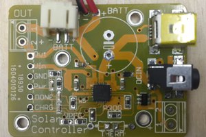
In this Hackaday project, I explore possibly using the AEMLIC Solar Harvesting board to harvest energy from a solar cell, store it in a 250F lithium ion capacitor, and provide the stored energy to a Raspberry Pi Pico. The Pico will sleep (some form of deep-sleep consuming little or no energy) between games.
I've started work on this and have already gone through some initial challenges. In this Hackaday project, I will write about some of these, starting with how to solder header pins onto the AEMLIC castellations (a significant challenge given my limited soldering ability).
 TM
TM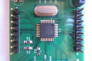
 Andrew Retallack