 John Forsyth
Review of Objectives
The objective of
this project was the design and creation of a home monitoring system.
It has several sensors throughout the home, which measure various
quantities and report them to a Raspberry Pi. The Raspberry Pi then
presents this data on a webpage, which allows for viewing of
information on trends occurring in the home. It also functions as an
alert system that makes the user aware of any unauthorized entry to
the home or the presence of fire. In the case of fire, the system
also controls parts of the home to both unlock a door and turn on
lights.
Review of Deliverables
The deliverables
for this project included monitoring aspects of the home, control
systems for the home, hosting a website, and acting as an alert
system. The deliverables related to monitoring the home included
gathering information on light usage. As well as the air quality,
temperature, and humidity in the home. Occurrences of power outages
were also to be monitored. Detecting whether doors are open or closed
was also required. Finally, the system would also detect the presence
of smoke. The control system deliverables for the home included
engaging and disengaging an electromagnetic lock and turning on and
off lights. These controls were also to be used to cause the lights
to come on and the lock to disengage if a fire were detected. The
website was to be created to display the aspects of the home being
monitored and to display them in a user-friendly manner. Finally, the
system was to act as an alert system such the user is informed when a
door to the home opens.
Technical Implementation
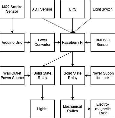
The first step in creating this project was setting up the Raspberry Pi 3 B+, and ensuring that it would boot successfully. Next, the BME680 sensor was attached to the Raspberry Pi. This task required soldering female headers to the BME680, and then connecting wires from these headers to their appropriate pins on the Raspberry Pi. In order, these pins are 1,3,5, 7, and 9. These specific pins were selected as they provide the sensor both power and I2C communication with the Raspberry Pi.
A program was written in Python to read the environmental information sent from the sensor. Using Python was a learning experience throughout the entirety of this project, due to only having used it to create one program prior to undertaking this project. To read data from the sensor a Python library supplied by the manufacturers of the sensor was included in the program.
Once the information could be read from the sensor, it was necessary to figure out a means of storing it in a database. MySQL was selected as the database software for this project due to its online presence and thorough documentation. MySQL was another major learning experience throughout this project. As a complete novice, it required much trial and error before the necessary level of competency was achieved to create a location for the BME680 data to be stored. Next, the Python program used to read the sensor’s information was altered so that it would send this information to the appropriate MySQL table. This was achieved through the use of a library called mysql.connector.
The next step in the project was displaying the stored environmental information on a webpage. To accomplish this, an Apache server was created on the Raspberry Pi. Luckily, its creation was far more straight forward than other aspects of this project and didn’t have a large learning curve for a complete novice. Once set up, the software broadcasted a webpage on the local network. To alter what appeared on the webpage, the Apache server’s default index file was edited. Through a combination of HTML and PHP (as well as mysqli which allows for PHP to interface with MySQL) it was possible to edit this file such that the webpage displayed the MySQL table containing the environmental information log. Although not part of the original proposal, the environmental monitoring presented on the website was expanded upon ...
Read more »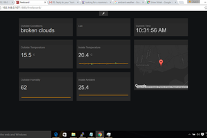
 Brenda Armour
 Inderpreet Singh
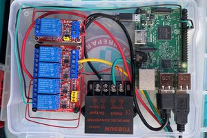
 blinkingthing
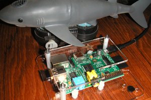
 Alan Campbell
Have you considered Adafruit MQTT? Monitor, record and control from anywhere in the world. It takes seconds to set up a HMI compared to a web page. I do both.
https://sites.google.com/site/nodemcu12e/home#h.bagvjtiwx7l3