 ElectroBoy
I made some projects using IR sensors and NEC protocol. Still, I don’t have a cool interface to decode the remote data. Most of the basic IR remote work on NEC protocol which used 32-bit value. NEC protocol has 8-bit address, 8 bit inverse of address, 8-bit data and its inverse. To decode this data, we only need a very few parts with a microcontroller. This decoded data is used in other projects like IR remote control car, DIY light remote, fan remote and to make a universal remote-control system.
I will convert the circuit into a PCB prototype shield. So that it is easy to decode the data whenever required. Just plug your microcontroller, sensor and battery. And I am using JLCPCB PCB prototype service for a long time. Honestly speaking it is the best reliable service offering 5PCBs in just $2 and 10 for $5. For this we need an Infrared Receiver sensor, here I am using TSOP1738 for these reasons.
TSOP1738 Receiver:
The TSOP17.. – series are miniaturized receivers for infrared remote-control systems. PIN diode and preamplifier are assembled on lead frame, the epoxy package is designed as IR filter. The demodulated output signal can directly be decoded by a microprocessor. TSOP17.. is the standard IR remote control receiver series, supporting all major transmission codes. Get the more information from the datasheet.
- Photo detector and preamplifier in one package
- Internal filter for PCM frequency
- Improved shielding against electrical field disturbance
- Output active low
- Low power consumption (3.3 to 5.5volts @ 10mA)
- High immunity against ambient light
- Continuous data transmission possible (1200 bit/s)
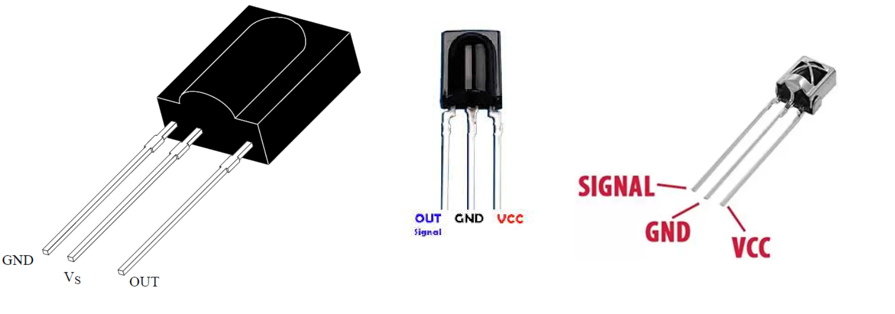
And don’t get confuse in the pin description of the TSOP series. You can follow the above given picture for better understanding. Pins of different packages are not the same but do the same job.
Components used:
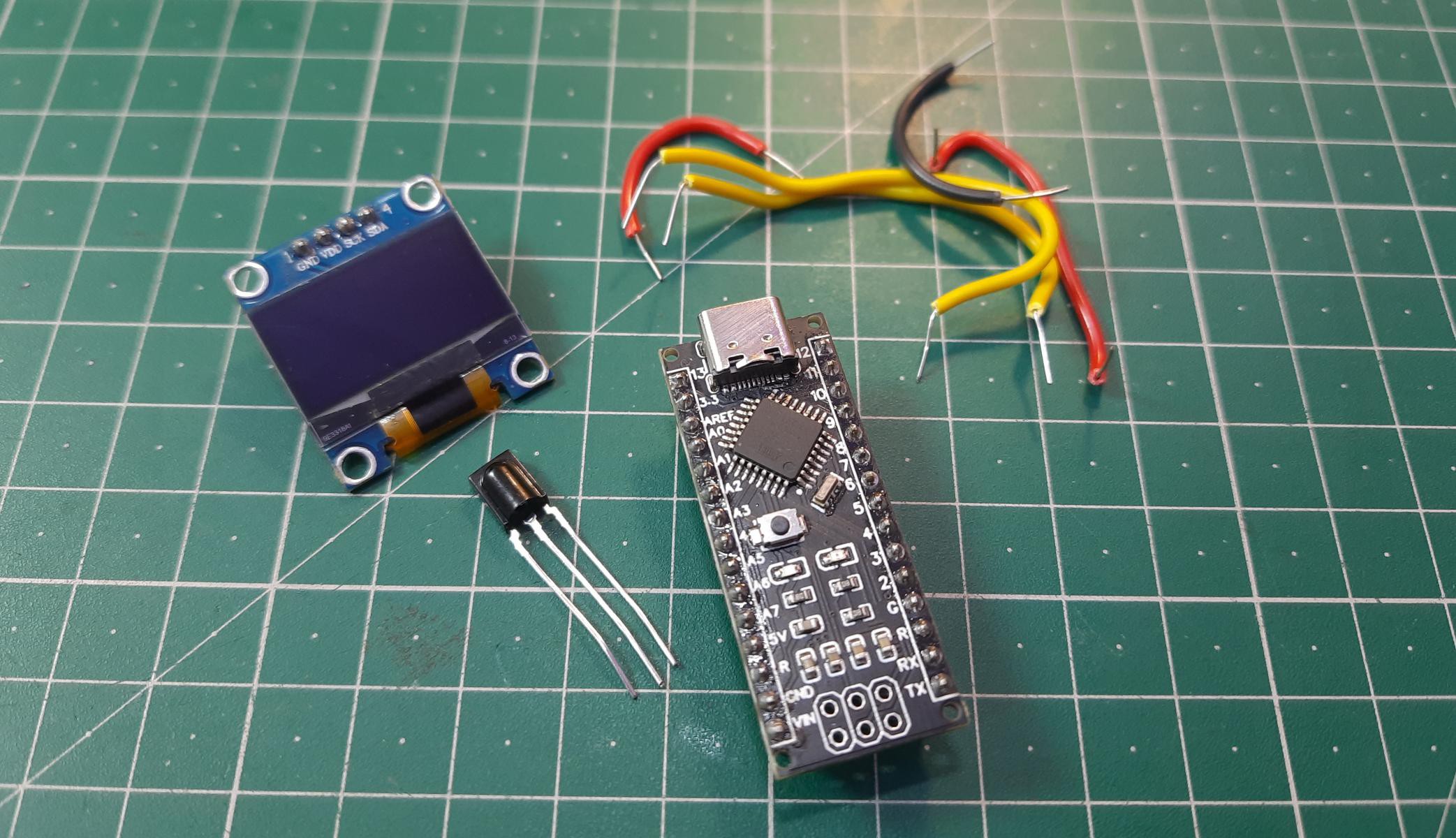
1) TSOP1738
2) Arduino NANO
3) SSD1306 0.96” display
4) 5V power supply
5) Custom PCB
Circuit diagram:
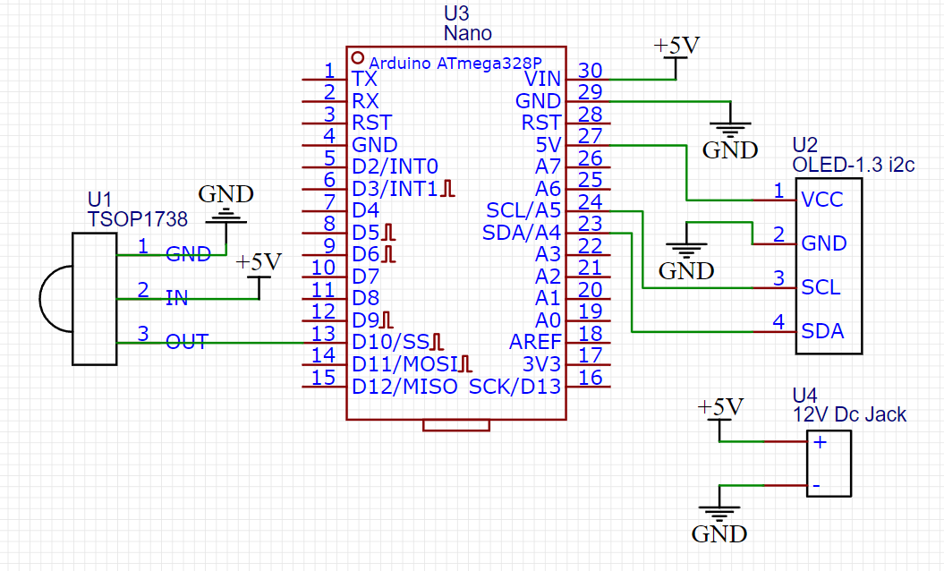
The circuit is designed with small I2C OLED screen. 4 wire interface minimized the wiring and overall schematics. SCL and SDA is connected to A5 and A4 of Arduino respectively. TSOP1738 has 3 pins, 2 for the power input and one for data output. And Output data from the sensor is in the digital form so we can use Arduino in digital read mode and there are some specific libraries which can convert/ decode the data into respective HEX and decimal form.

To reduce the efforts, you can use the PCB prototype shield made by me. The project is very easy but there are very less chances of working without proper libraries data.
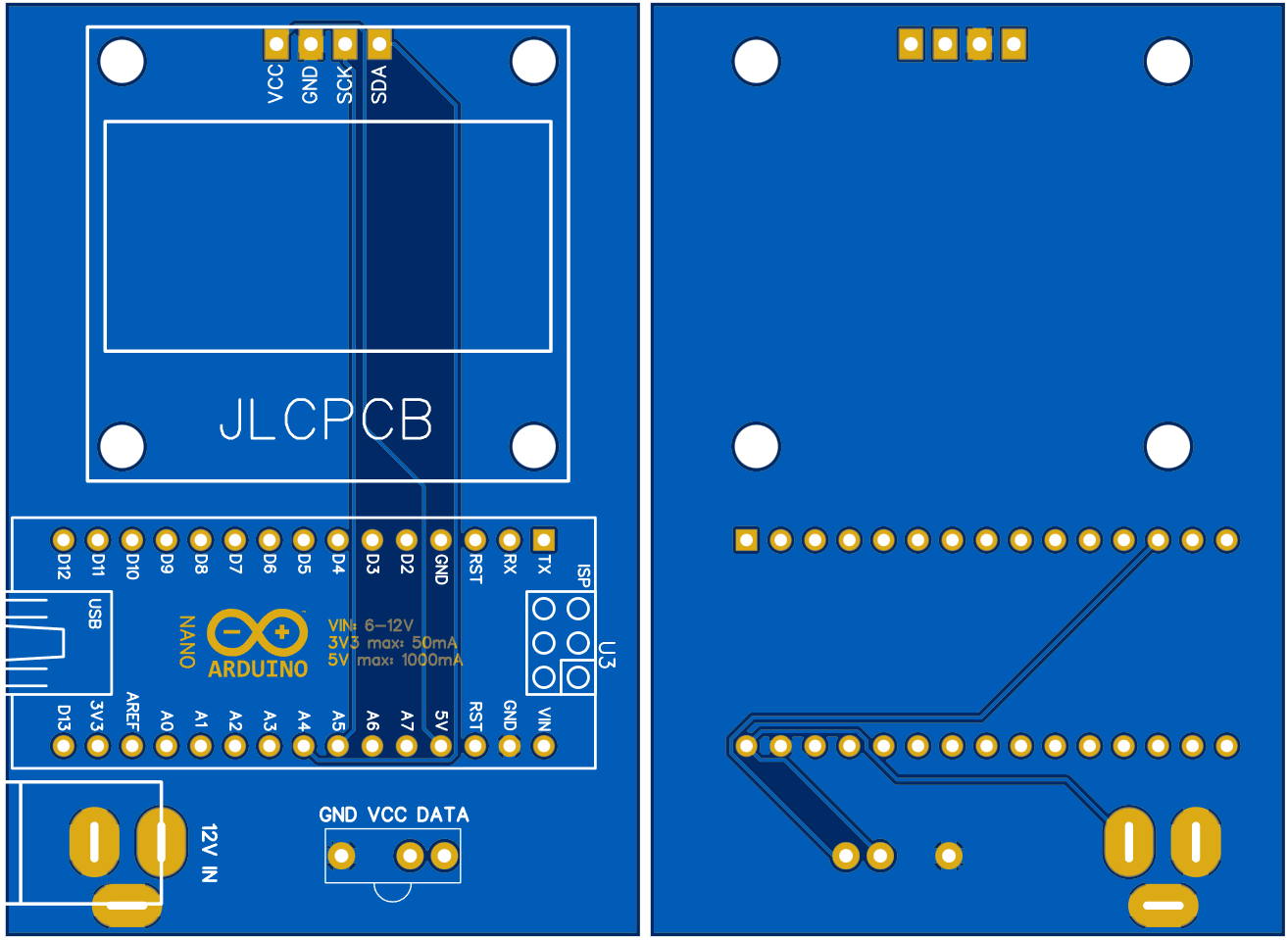
PCB designs:
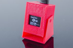
I made the shield so that you can plug the microcontroller after programming then the IR receiver sensor and display. And we are ready to after powering the system. No need of any external components. Even this project can be made without screen, serial monitor window inside Arduino IDE can do the same job.
Download the Gerber files from here and upload them to JLCPCB, Sign-up using this link to get $54 coupons and place your order just in $2 for 5 PCB boards.
Code:
/* hello guys here I am using older versions on IR library so please download and install all the previous version
* The link to download preferred library is:
* This code is made by Sagar Saini/ YouTube: Sagar networks
* Any questions or queries DM me on Instagram Saini_sagar_7294.
* Explore my website for more interesting projects: www.circuitkicker.com
*/

#include <IRremote.h>
#include <Wire.h>
#include <Adafruit_GFX.h>
#include <Adafruit_SSD1306.h>

// Declaration for an SSD1306 display connected to I2C (SDA, SCL pins)
#define OLED_RESET 1
Adafruit_SSD1306 display(128, 64, &Wire, OLED_RESET);
const int RECV_PIN=10;
IRrecv irrecv(RECV_PIN);
decode_results results;

void setup()
{
Serial.begin(9600);
irrecv.enableIRIn(); // Start the receiver
irrecv.blink13(true); // Led will blink on receiving each signal
display.begin(SSD1306_SWITCHCAPVCC, 0x3C); // try 0x3D also if OLED is not working
display.clearDisplay();
...
Read more »
 Sagar 001
 ZaidPirwani
 ACROBOTIC Industries