• 2.- Shocking problem

    guilldeas09/13/2022 at 20:16 0 comments

    The remaining problem to solve was somewhat more dangerous, the machine's casing was live and would often shock the audio engineers, to look for the fault the amplifier was dissasembled and  probed while running idle.

    This showed the power stage heatsink was live at 100V DC. 

    It should be noted that this should not necessarily always be a cause for concern since some amplifier heatsinks are live by design, this is because power MOSFETs dissipate their heat better, away from the die and into the heatsink, if theres a direct connection from it's die to it's metalic pad which unfortunately places the die's voltage into the heatsink.

    However this could not have been intended since all of the components attached to it had been electricaly isolated with silicone and mica pads. This indicated some isolation had failed and the fault was found probing for shorts (with the machine shut down) with between the components and the heatsink.

    The rail tracker transistors (pictured above) were the ones at fault, their mica pads were replaced, new thermal paste was applied and thus the voltage dissapeared from the heatsink and casing.

    Finaly the machine was given a cosmetic treatment, the worn out paint was sanded down and repainted, the frontal sticker was sourced and replaced.

  • 1.- Temperature problem

    guilldeas09/13/2022 at 19:33 0 comments

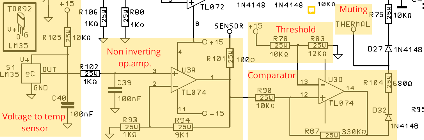
    The temperature problem was tackled first, apparently the machine was triggering the temperature protection unnecesarily so I gathered a general understanding of it's circuit from the schematic (seen above).

     This machine is puerly analog and the fault detection consists on an LM35 IC thermaly coupled with the power stage heatsink, this component outputs a voltage such that:

    This is then followed by a Low Pass filter, presumably to filter out high frequency noise and avoid unnecesary triggering. It's output goes into an op.amp in a non inverting configuration with gain 10 which boosts the signal level to:

    After the signal is conditioned a final stage sets a threshold for triggering, this is achieved by comparing 8.18V generated by a voltage divider against the signal with an op.amp in a comparator configuration. 

    This sets the protection temperature at 81 ºC which after measuring the heatsink temperature to be much lower (with a PT100) proved that the machine was triggering unnecesarily.

    The comparators output signal, labeled as THERMAL, drives the gate of a JFET (not pictured) which, upon receiving a high level input, ties the input of the amplifier to ground muting the machine and thus allowing the power stage to cool down avoiding a catastrophic failure. 


    After understanding the muting mechanism it was inspected for faults where it was discovered that the ribbon cable carrying the analog temperature signal had been teared (tear not visible on picture), this left the voltage floating at a level equivalent to around 1000 ºC! No wonder the machine was trying to protect itself...

    The teared part was cut and resoldered on to the PCB.