 Brian Brocken
Video:
thank you to PCBWay for sponsoring this project. More info about them can be found in the speed controller section further down.
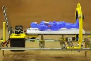
Here are some specifications of the gearbox:
Max tested torque at 12V: 41.3kg*cm or 4N*m
Reduction ratios:
Circular spline teeth amount: 50 teeth
Flex spline teeth amount: 48 teeth
Small GT2 pulley: 16 teeth
Big GT2 pulley: 36 teeth
Reduction ratio strain wave gear: (48 - 50)/48 = -0.0416
1/0.0416 = 24.038
Reduction ratio = 24.038:1
Reduction ratio belt drive: 36/16= 2.25
Reduction ratio = 2.25:1
Total reduction ratio = 54.0855:1
Electrical specifications:
Motor type: 775 brushed motor (see parts list)
Motor Voltage: 0-24VDC
Idle power consumption at 12V: 10W
PCB rated voltage: 12VDC
PCB rated voltage with jumpers for Arduino power supply removed and replaced by a separate DC-DC converter module: 24VDC
Working principle
A strain wave gearbox has 3 main components:
-Wave generator
-Flex spline
-Circular spline

The wave generator (green) generally is the input side of the gearbox and has the highest RPM. The wave generator is being used to deform the flex spline and make the teeth interlock with the fixed outer circular spline (blue). The flex spline (red) is generally the output of the gearbox and has the lowest RPM. One full rotation of the wave generator will move the flex spline 2 teeth in the opposite direction.
Circular, flex spline and wave generator design
The design of the teeth for the circular and flex spline turned out to be a little harder then expected. I originally wanted to use double helical gear generator to create the teeth but the teeth ended up interlocking over the complete circumference of the splines, even with a 4 teeth difference between them. Then I tried regular spur gears but these gave the same problems as the double helical teeth. It turns out strain wave gears don't use regular teeth but a much shorter and more straight tooth profile.
After the tooth profile was figured out I 3D-printed a first test with a flex spline in PLA. This initially seemed to work pretty good but after a few minutes of turning the flex spline made a few weird noises and pretty much exploded. So this was not going to work. Then I tried printing it TPU filament (flexible filament) which worked a lot better. The dimensions and structure of the flex spline and wave generator needed to be modified a bit in order prevent the flex spline from slipping inside the housing (tighter tolerances needed).
The wave generator originally used 4 bearings to push the flex spline in the outer circular spline but when I switched the material of the flex spline from PLA to TPU I changed this number to 6 to make the contact area bigger and prevent slipping of the flex spline.
Performance
Originally the limiting factor of the gearbox was belt reduction used to drive the wave generator. After changing out the plexiglass lid for a 3D-printed lid and adding an extra motor spacer between the case and motor this issue was resolved. The limiting factor now is the motor itself in combination with the reduction ratio of 54:1. The strain wave gearbox has a stall torque of around 41.3kg*cm or 4N*m.
Speed controller
First of all a big thank you to PCBWay for sponsoring this project. Due a price drop in raw materials, PCBWay can now provide PCB's at a reduced price. Use my referral link to get a 5$ discount when you sing up as a new user: https://www.pcbway.com/setinvite.aspx?inviteid=586251
To control the speed and direction of the motor I designed a custom Arduino Nano based PCB. The PCB features a reverse polarity circuit, a voltage divider to measure the supply voltage, some resistors for LEDs and some header pins to connect the PCB to the IBT2 motor driver.
The gerber file for the PCB can be found in the files section on this...
Read more »
 Mrinnovative
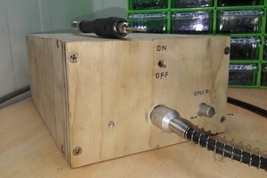
 youkito1991
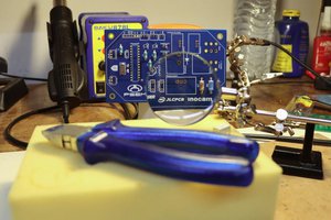
 psemportugal
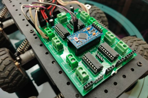
 Jithin Sanal
well done!