 flamefire
What you will see in my project.
- Mistakes
- Mistakes
- Small Progress
- More Mistakes
and then we loop until we are done with the project.
The plan!
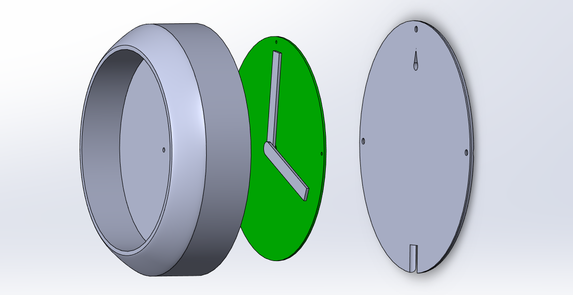
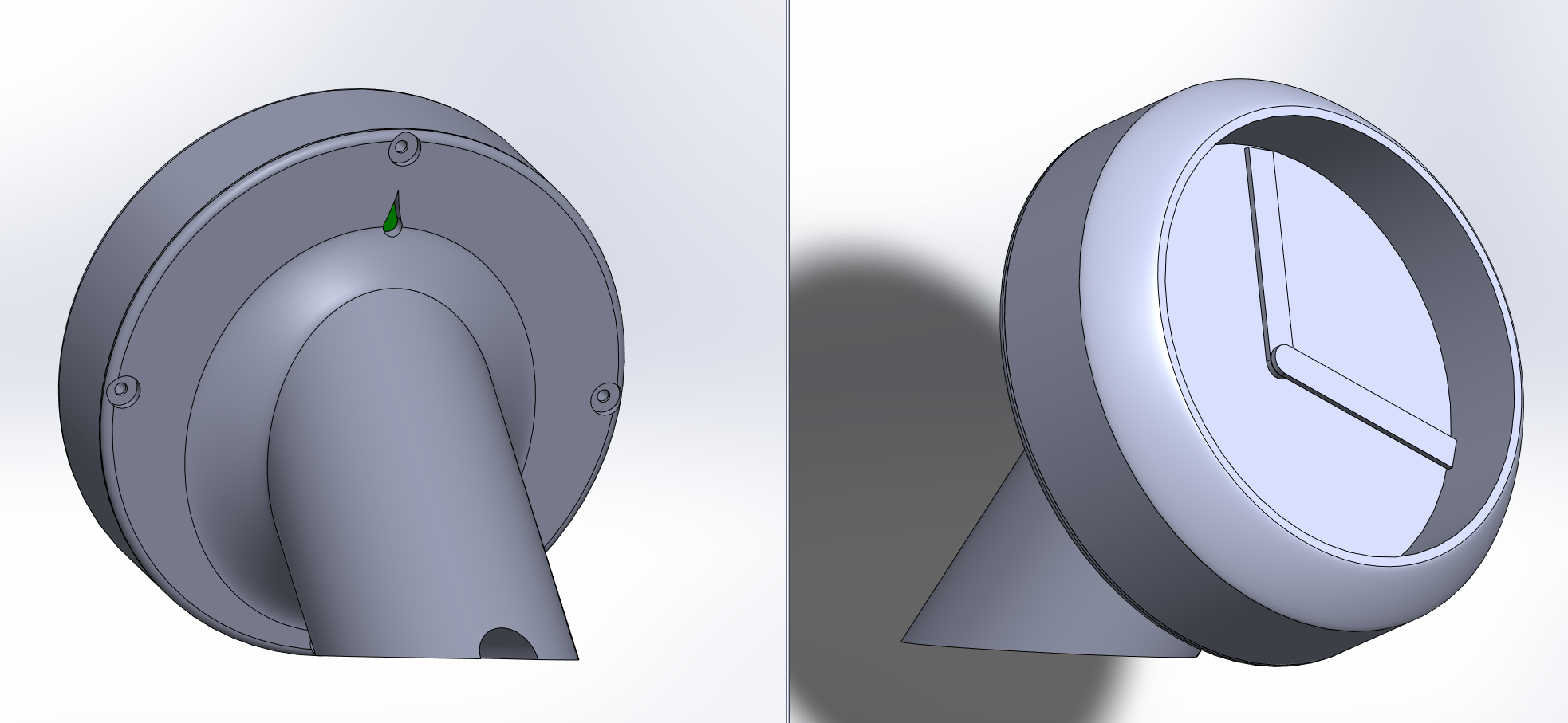
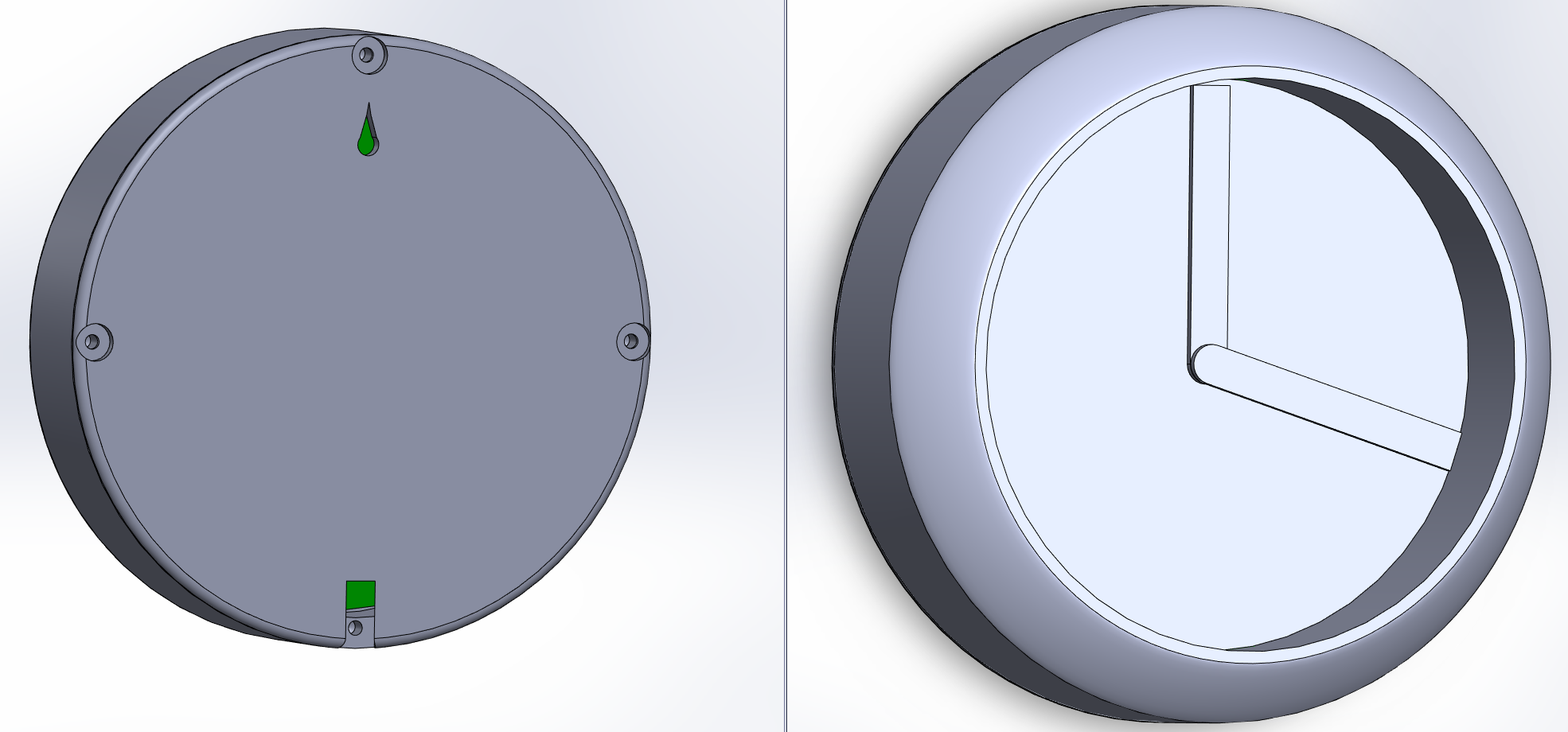
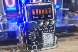
To make a smart clock with some cool formations of the pointers!
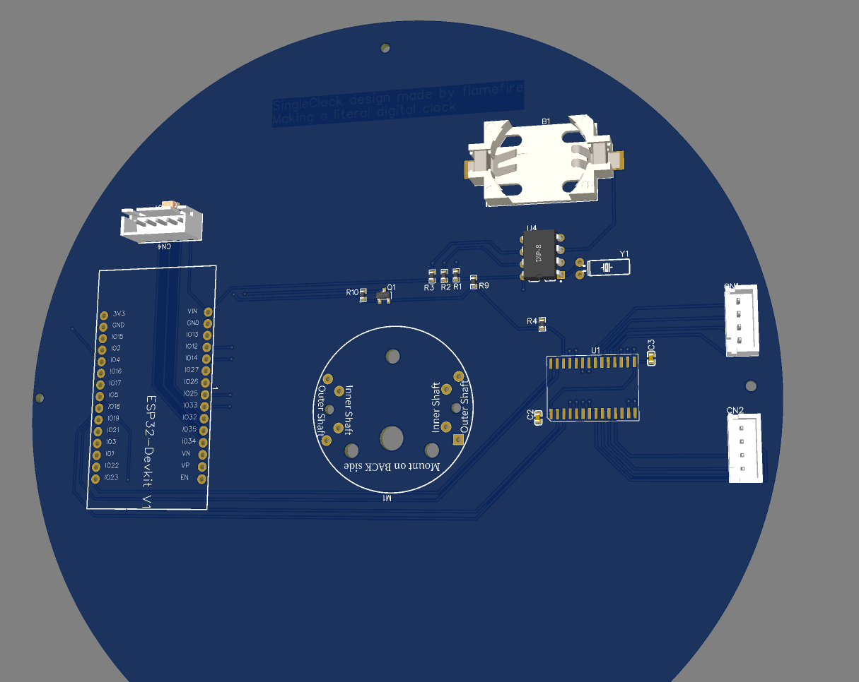
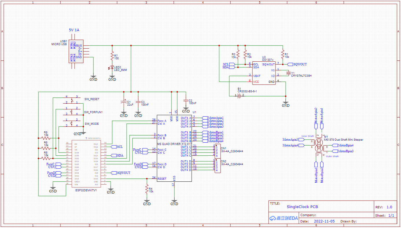
- I will use ESP32 as my board. Why you might ask? They have wifi, bluetooth, many IO pins for its size and they are quite inexpensive when bought from china.
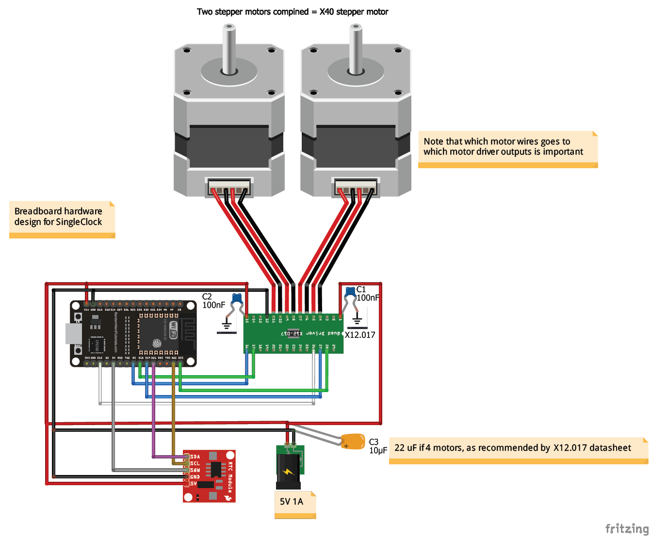
- For the motors I first tried to design my own dual shaft stepper motor with two small stepper motors and many gears! Then after designing for a small month, I realized that China obviously already have this. I will be testing the X40 china copy of Switec and the less expensive BKA30D-R5.
- To keep track on time I will either use WiFi or RTC.
- To keep track on the pointers location, I will try to brute force a software solution with saving the steps in the EEPROM, if this fails I could probably use a retro reflector sensor.
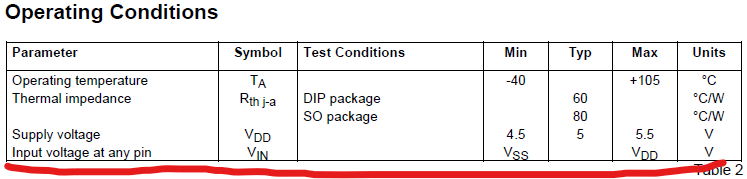
- To get familiarized with driver motor, I will use the infamous x12.17 stepper driver which also allows microstepping. This allows me to cut the I/O pins needed in half. The driver can control two double shafted stepper 4 wire motors. A double shafted motor, is basically two single shafted motors that use 4 wires, so in total 16 motor wires can be controlled with the x12.17. Each motor needs a direction and how many steps it should take so that's 8 pins, hence the I/O pins gets cut in half.
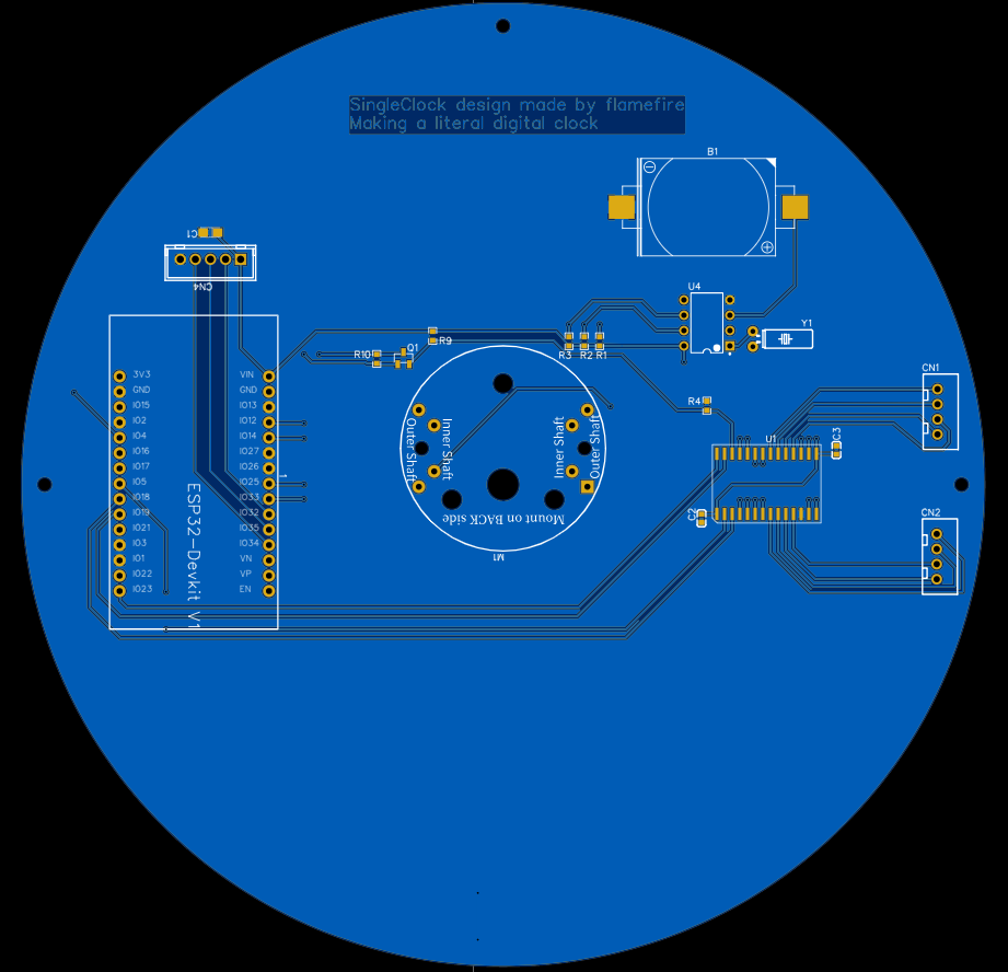
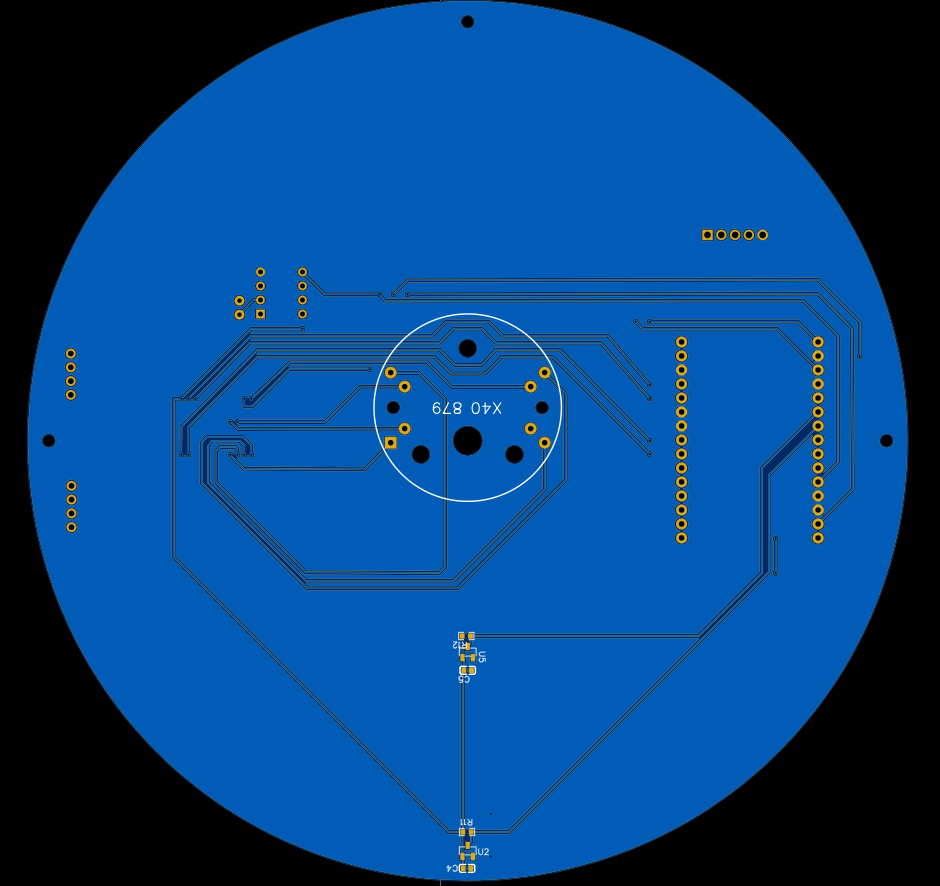
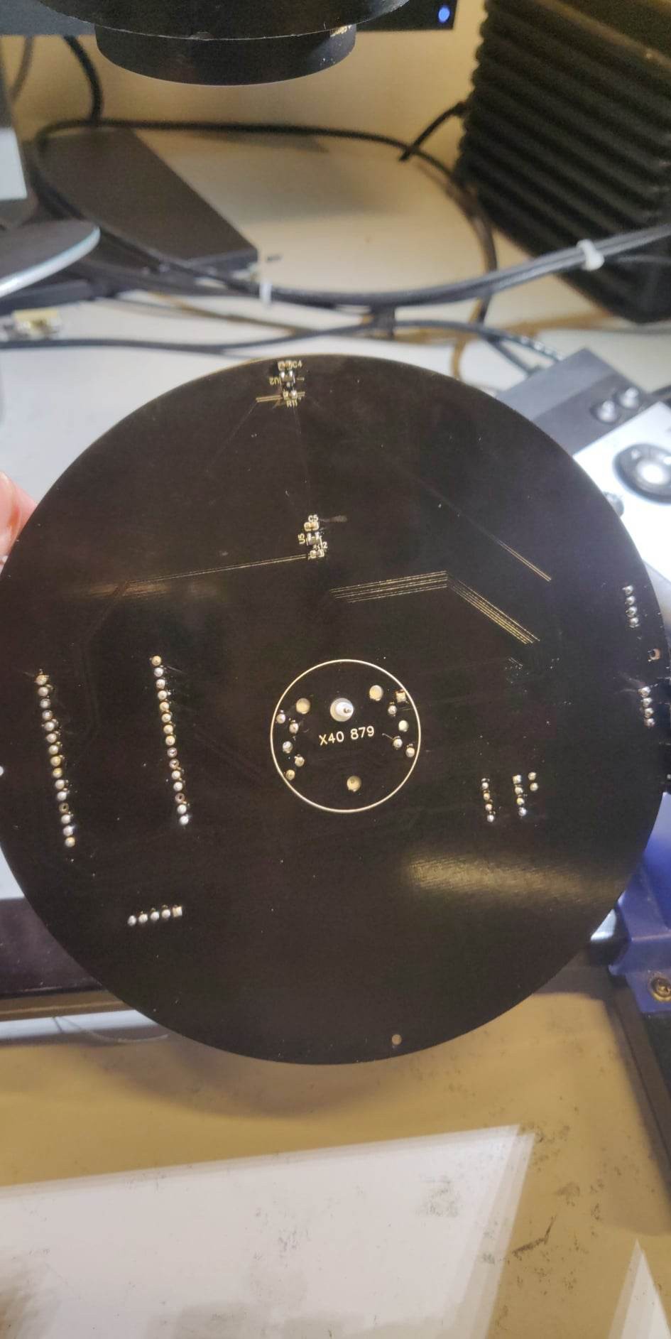
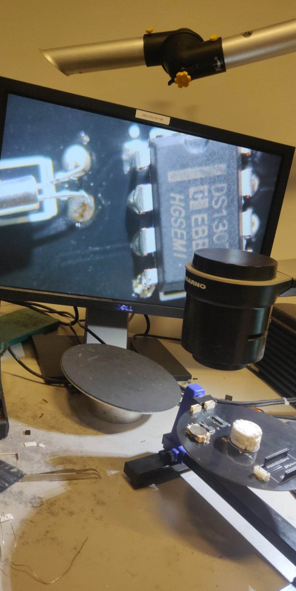
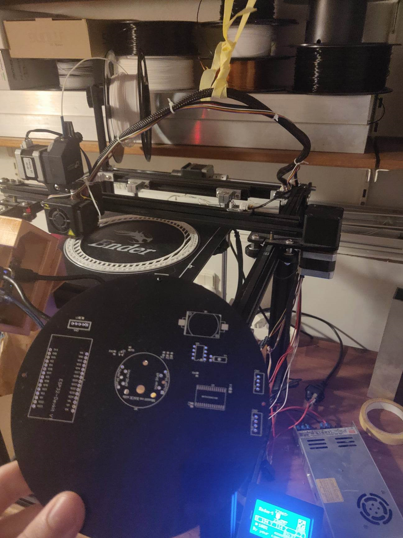
I might make some sketchy PCB design and solder a prototype.
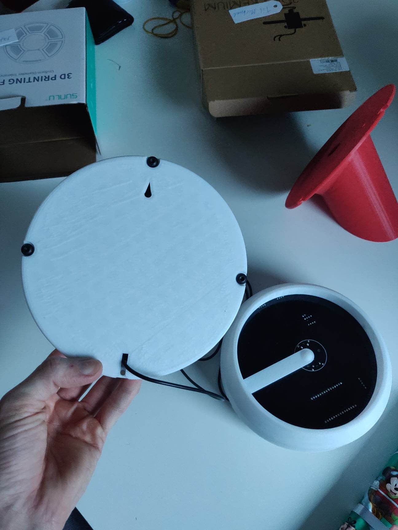
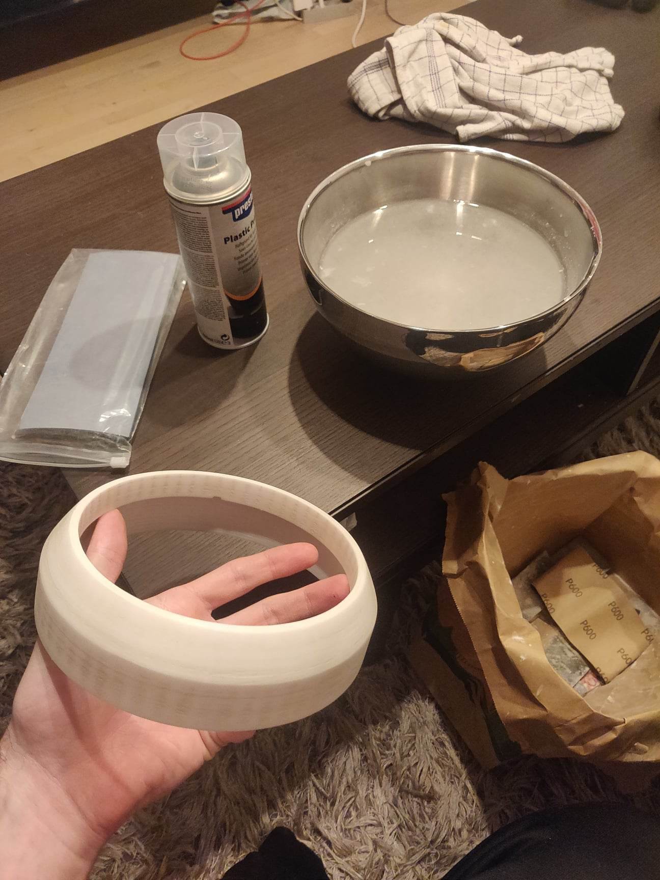
Then we take our hammer and mallet and put it together, how hard can it be?

 Yakroo108
 Michael Möller
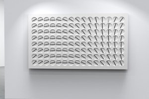
 opeRaptor