 Sagar 001
It is very easy to calculate the hexadecimal equivalent to a decimal number using dividing by 167 method. But this method is very long and sometimes very confusing when comes to large numbers. here I have a Arduino based decimal to hexadecimal converter. But let's know more about hexadecimal number system and why it was designed to work with popular intel microprocessors in 60's.

first we will know how to convert decimal into hex manually and then use Arduino based system to make a calculator project.
Hexadecimal number system:
Hexadecimal uses digits that more closely resemble our usual base-10 counting system. And through this more variation in data can be represented using the same number of digits. In hexadecimal counting goes from 0 to F, and F represents the decimal number 15. So, by using less number or same number of digit variation more data can be stored.

Hexadecimal is the name of the numbering system that is base 16. This system, therefore, has numerals 0, 1, 2, 3, 4, 5, 6, 7, 8, 9, 10, 11, 12, 13, 14, and 15. That means that two-digit decimal numbers 10, 11, 12, 13, 14, and 15 must be represented by a single numeral to exist in this numbering system A, B, C, D, E, F respectively.
Converting decimal into hexadecimal:
Divide the digital number by 16 and keep the remainder separated. By following multiple division the remainder data gives the hexadecimal number information.

The remainder is calculated from below to upside and then to the base 16 finally give hexadecimal number representation.
Components Required:

- Arduino UNO
- 16x2 LCD with I2C
- 4x4 Keypad
- Custom PCB from JLCPCB
- Battery
Circuit diagram:
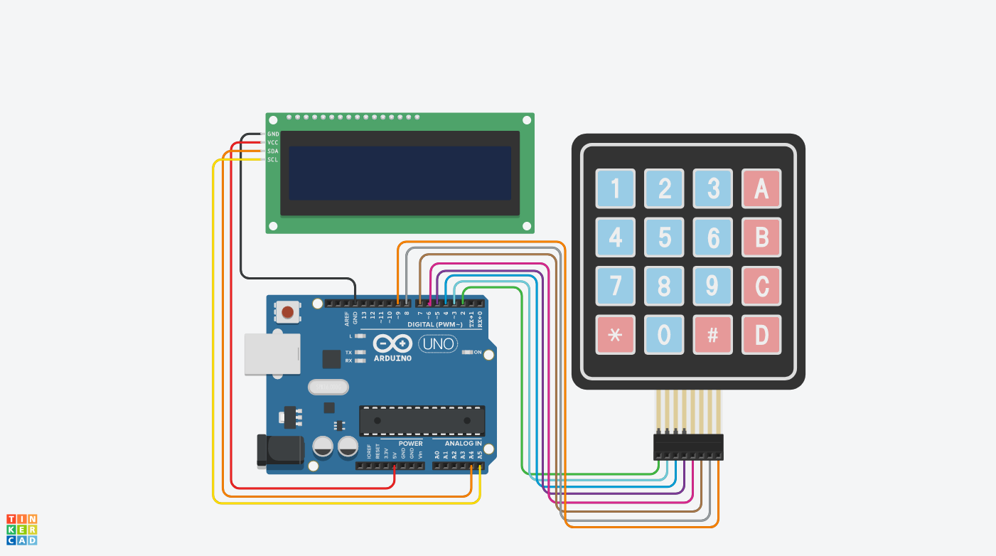
The circuit is made using an input 4x4 keyboard, an LCD display and an Arduino. The Arduino do all the calculation in real time and display the values on screen. Keypad has 16 inputs in which 0-9 are used for data input and C for reset. we are not using other buttons of keyboard for now.

Keyboard works on a matrix system only 8 connections are required to do all the wiring. For the screen we are using I2C interface which required 4 wires, two for the power and two for the data. Whole the system can be powered using a 9v battery.
PCB Shield:
I also prepared a PCB shield to eliminate the wiring connections. Just plug your hardware to the shield and we are ready to go. The power jack is mounted on top right side, it can be powered using same 9v battery. I used Arduino Nano here for better compatibility of pin headers.

You can try JLCPCB PCB prototyping service for your projects. JLCPCB is the one of leading PCB manufacturer from CHINA. Sign-up now to JLCPCB and get free new user coupons of worth $54. If you want to use these design then download from here. Or you can also try something different the circuit details with diagram are given above.
Code:
// including the libraries
#include <LiquidCrystal_I2C.h>
#include <Keypad.h>
#include <Wire.h>

// initialize the variables
const byte ROWS = 4;  //Four rows of Keypad
const byte COLS = 4;  //Four columns of Keypad
char key;
String decimalNum;
long decimalNumber;
String hexNumber;

//Define the symbols on the buttons of the keypad
char Keys[ROWS][COLS] = {

  {'1', '2', '3', 'A'},
  {'4', '5', '6', 'B'},
  {'7', '8', '9', 'C'},
  {'*', '0', '#', 'D'}

};

byte rowPins[ROWS] = {2, 3, 4, 5};
byte colPins[COLS] = {6, 7, 8, 9};

// create keypad and LCD objects
Keypad myKeypad = Keypad(makeKeymap(Keys), rowPins, colPins, ROWS, COLS);
LiquidCrystal_I2C lcd(0x27, 16, 2);

void setup() {

  // start Serial communication
  Serial.begin(9600);
  Serial.println("Electronics Champ");

  // initialize the lcd
  lcd.init();
  lcd.begin(16, 2);
  lcd.clear();
  lcd.backlight();
  lcd.setCursor(0, 0);
  lcd.print("Electronics");
  lcd.setCursor(0, 1);
  lcd.print("Champ");
  delay(3000);
  lcd.clear();
  lcd.setCursor(0, 0);
  lcd.print("D: ");
  lcd.setCursor(3, 0);
  lcd.print(0);
  lcd.setCursor(0, 1);
  lcd.print("H: ");
  lcd.setCursor(3, 1);
  lcd.print(0);

}

void loop() {

 key =...
Read more »

 Tony Keith
 vivek gupta
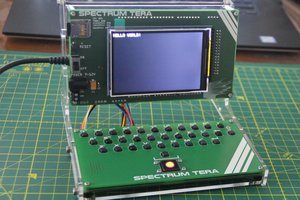
 M. Bindhammer
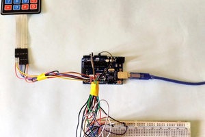
 Mrinnovative
pity it cant do the reverse!