 DIY GUY Chris
If you hate reading then a video could tell it all : Watch here
Here is a view of the needed tools for the assembly of the hardware.
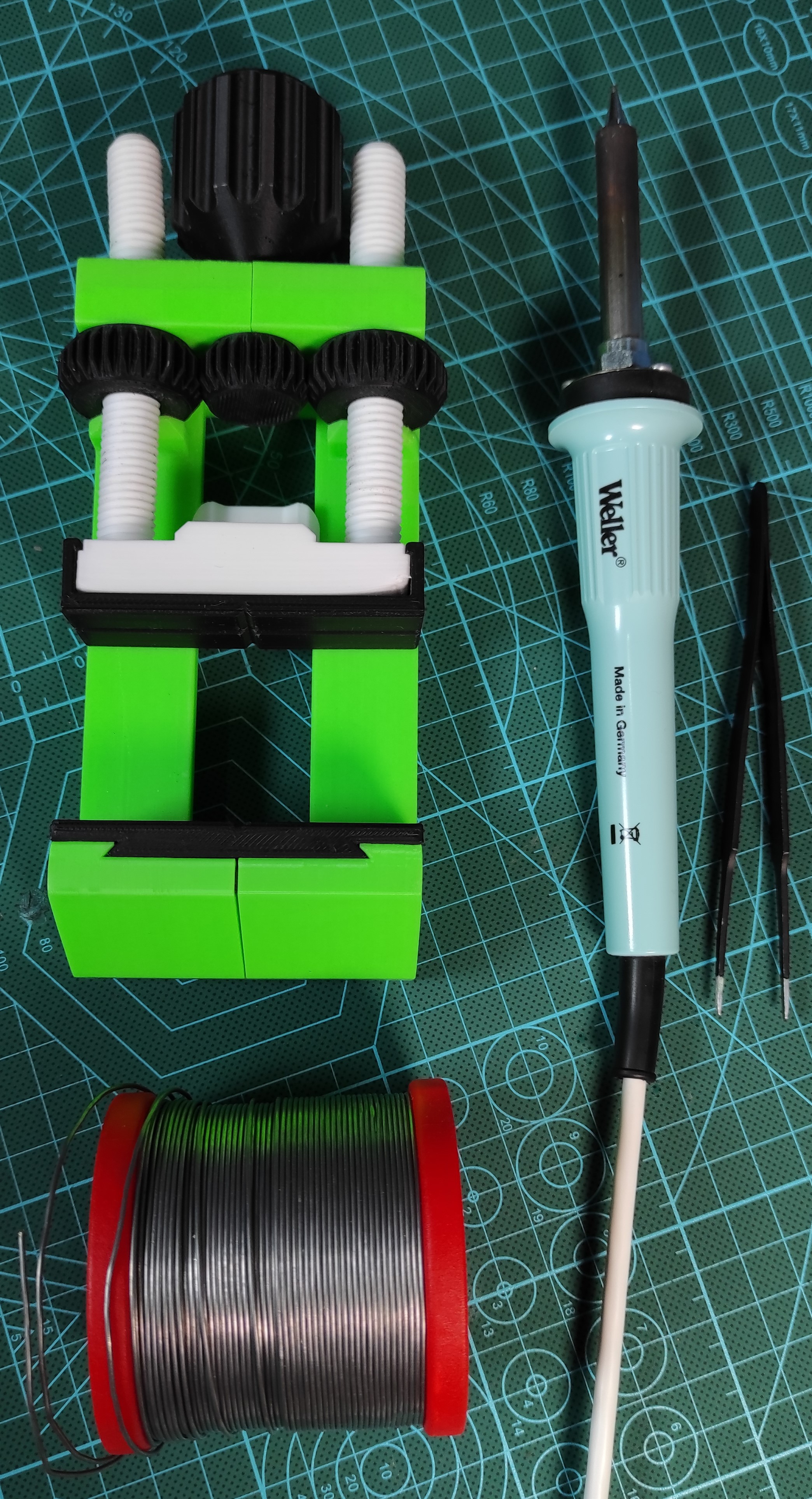
The hardware needed here is mainly used during the circuit assembly so you will use the Vise to hold the Circuit board the the tweezers will assist you placing the electronics components in their placements on the board, the solder iron and the solder core spool are obviously needed for the parts soldering.
Note
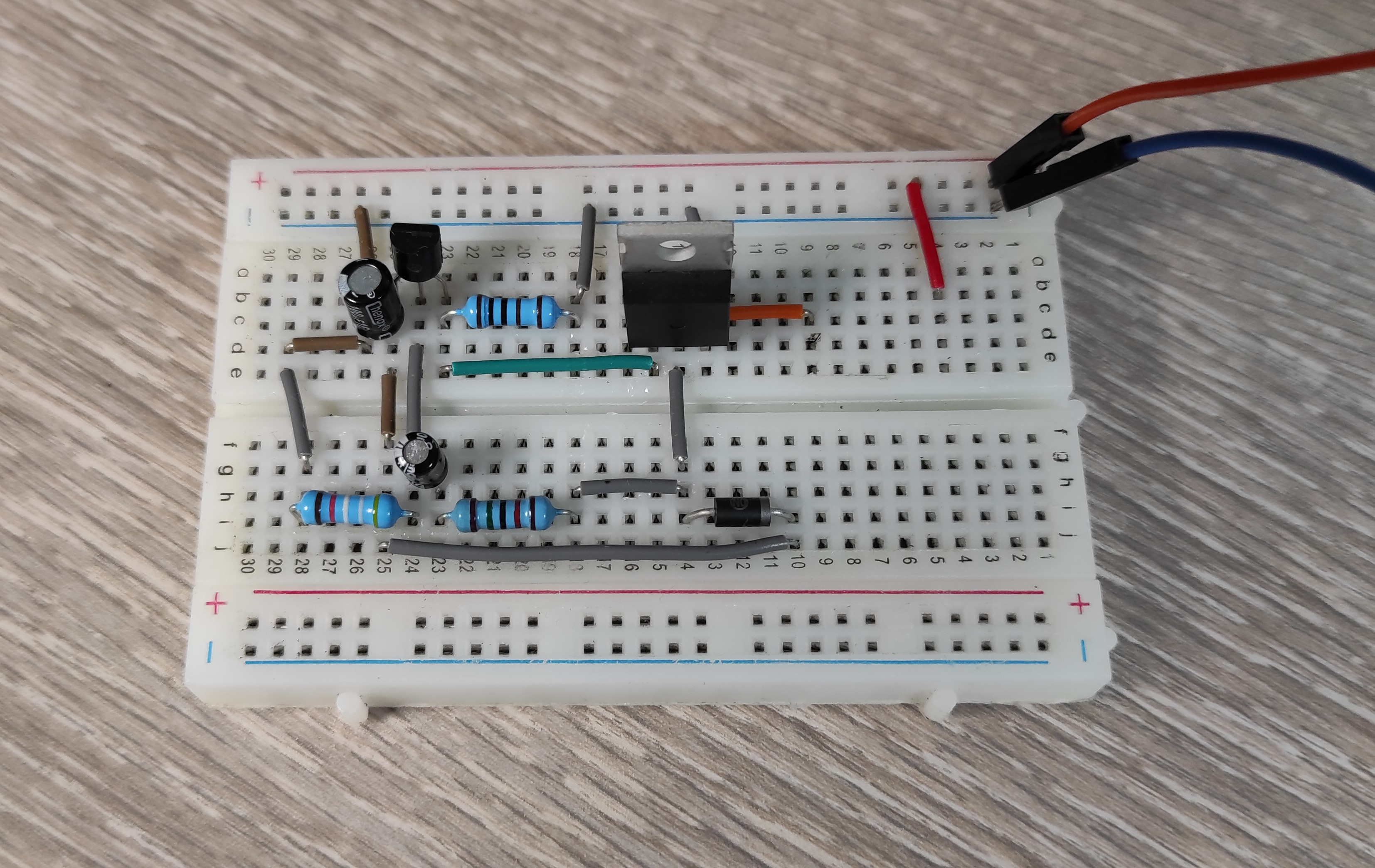
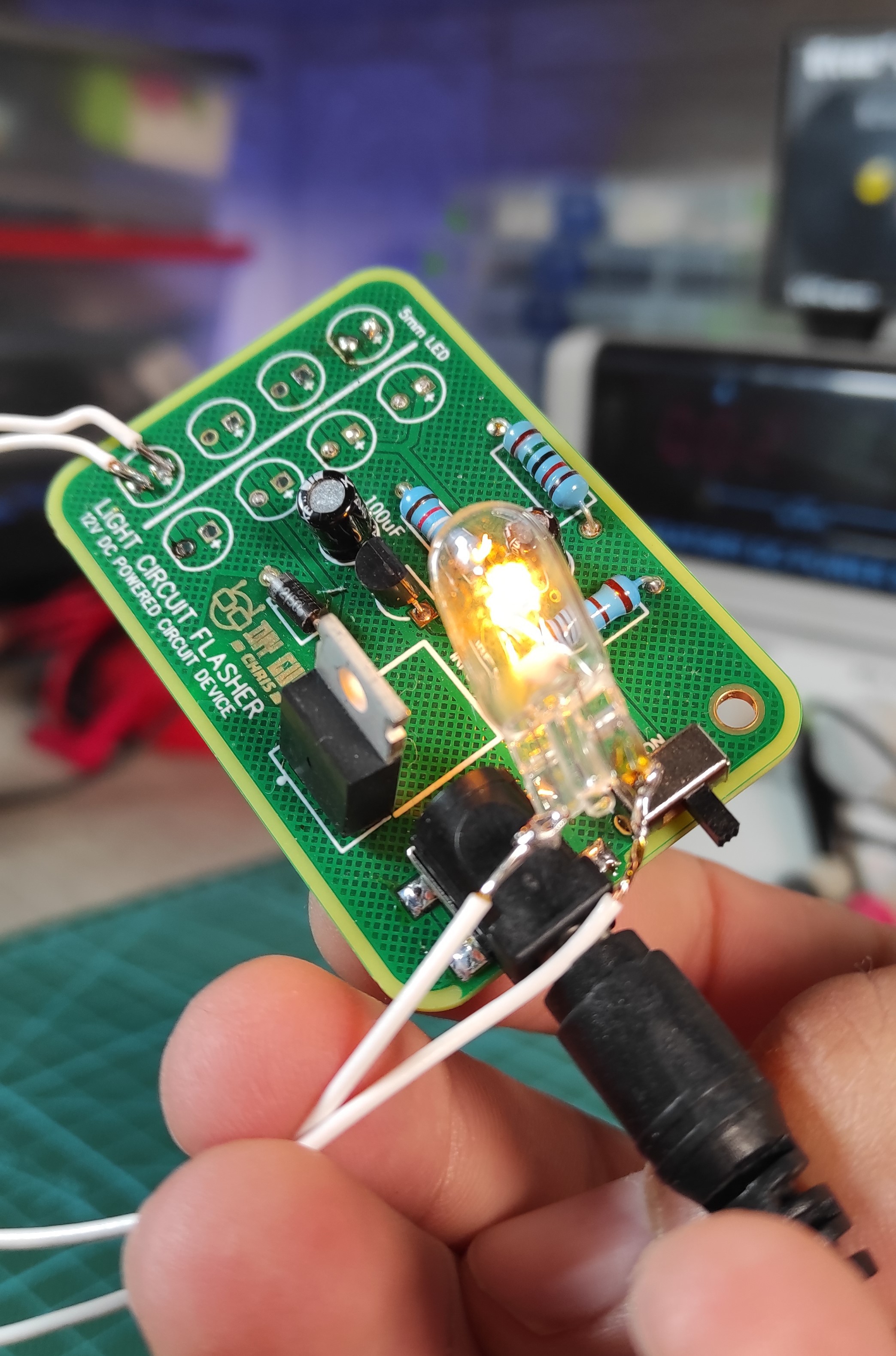
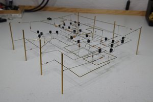
Before moving to the circuit design it is always recommended to test the circuit in a breadboard to make sure that everything is okay and you are using the appropriate components in the appropriate connection, I tried the circuit on my breadboard and I used 12V DC power from my "Lab Power Supply" as same as provided from car 12V battery source, remember that in our circuit we are aiming to flash 12V Bulbs not LEDs, the ones used in the schematic will represent the Bulb output connection since I can't insert Bulb icon so I used the LEDs symbol.
I got promessing results after getting the circuit powered from the 12V power entry and the Bulb started flashing in a defined frequency that you can adjust by adjusting the Capacitor value of C1 (100uF).
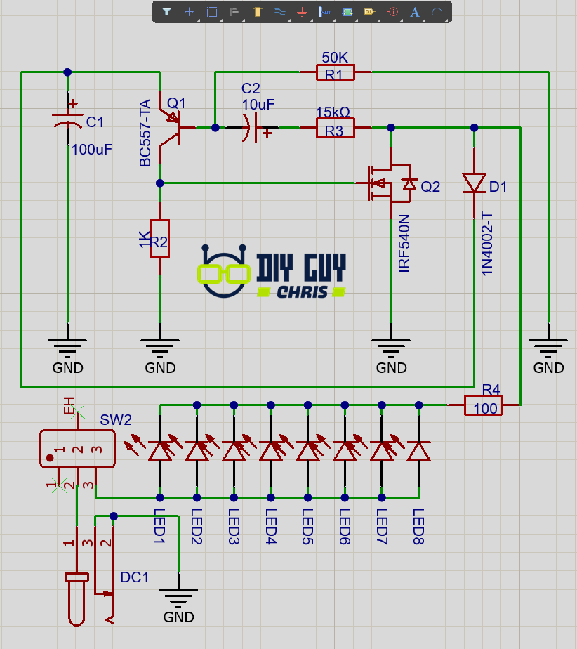
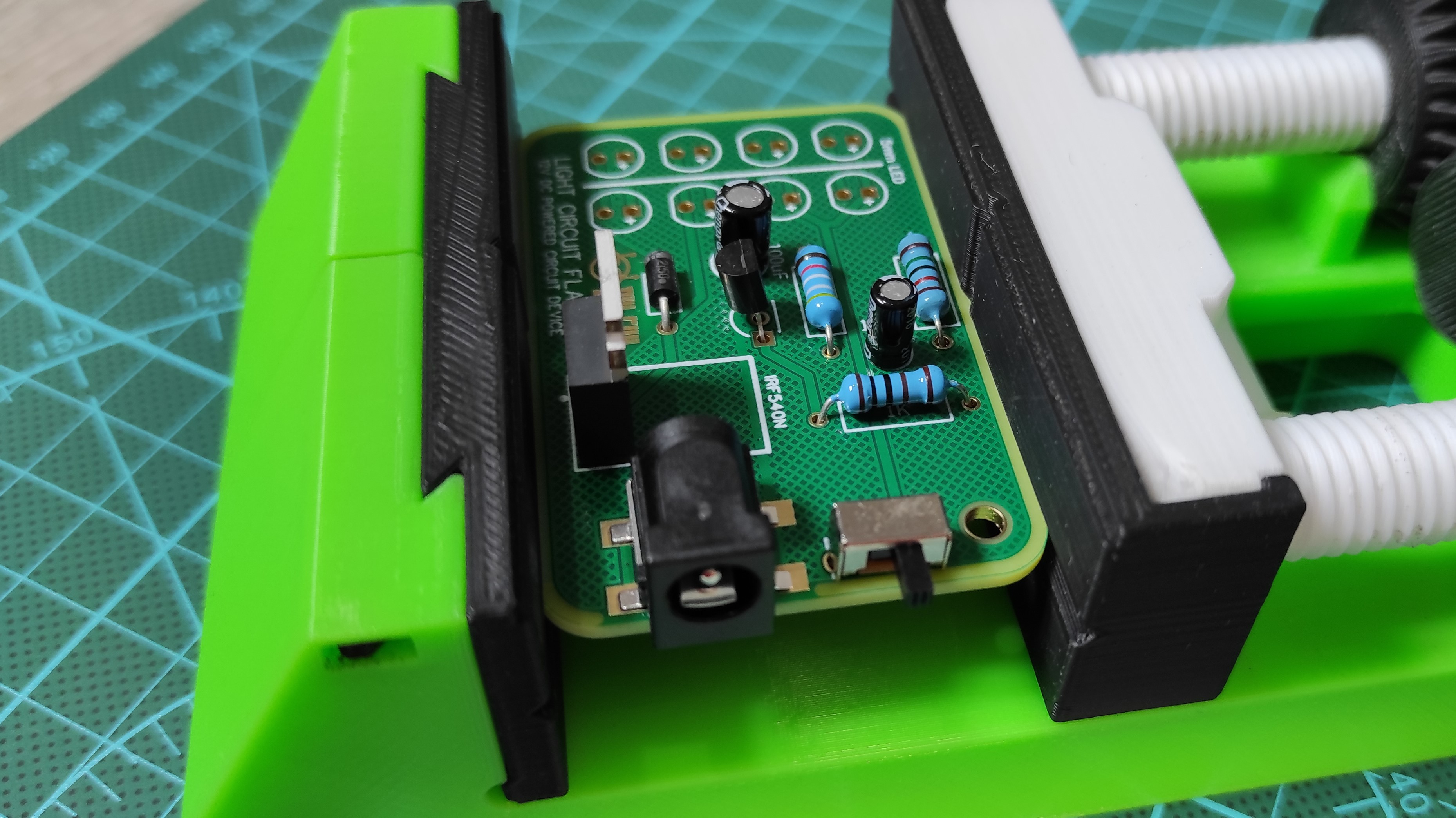
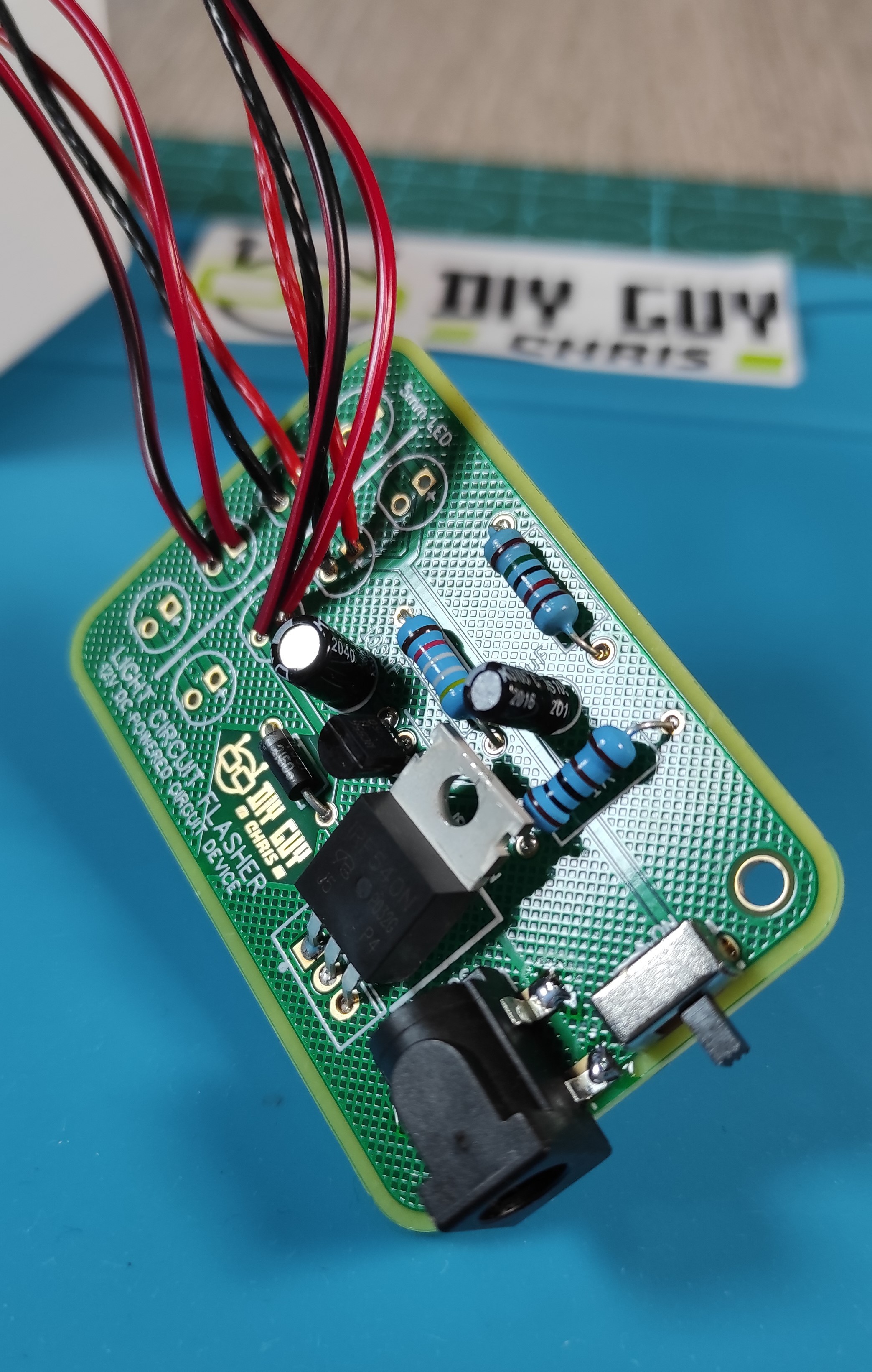
After getting the circuit tested I then moved to Altium designer to draw schematic of the tested circuit and then convert it into a PCB design, I added a Jack connector for power supply and a slide switch for On/Off control, the resistors are all 1/2W good enough to handle the Bulbs consumed power.
Since a simple transistor couldn't handle the current dropped by the Bulbs then I placed a power MOSFET IRF540 to control the output power if the Bulbs.
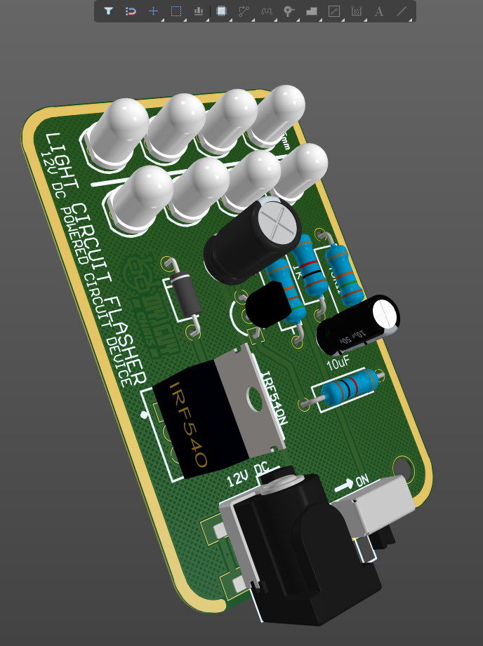
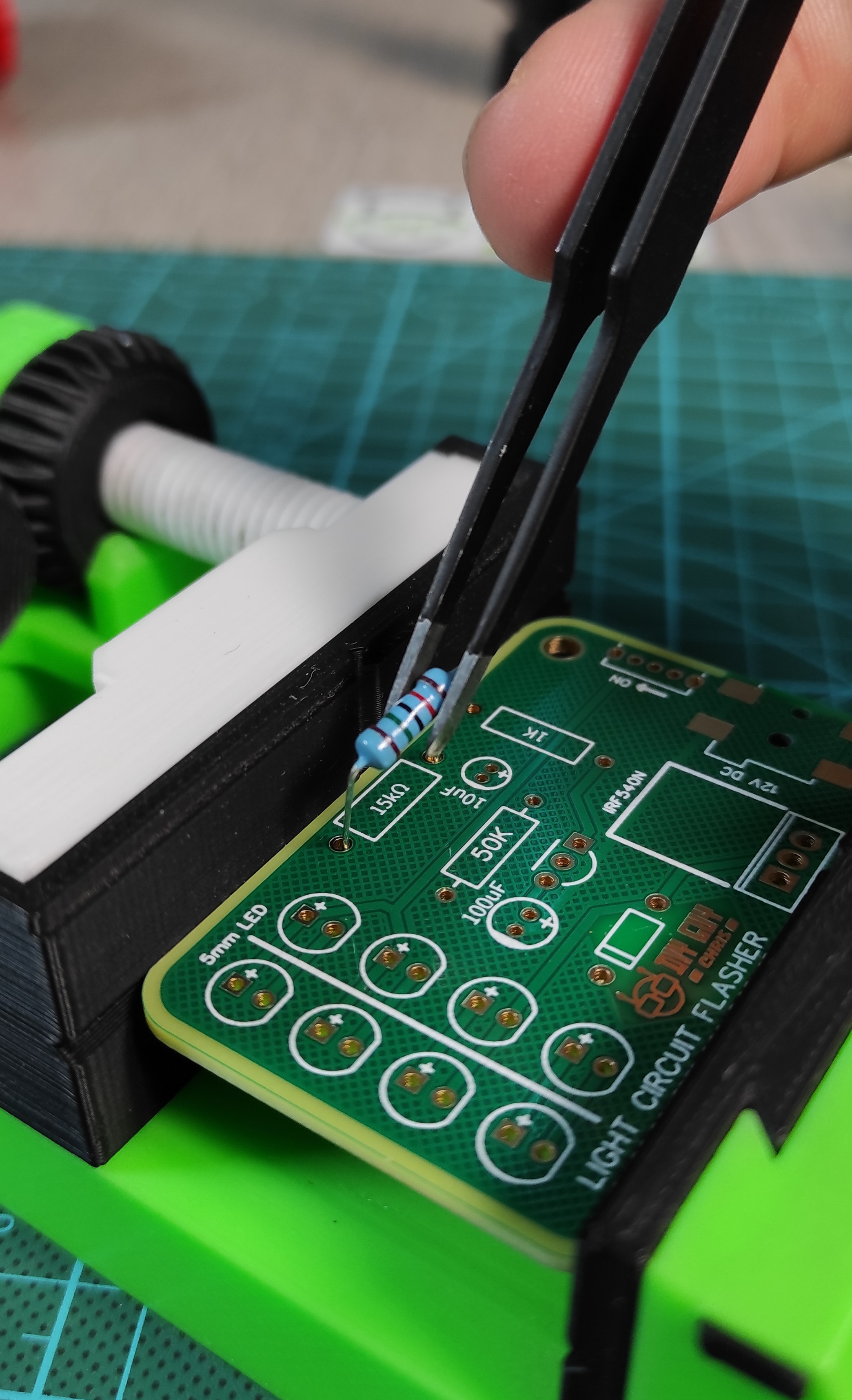
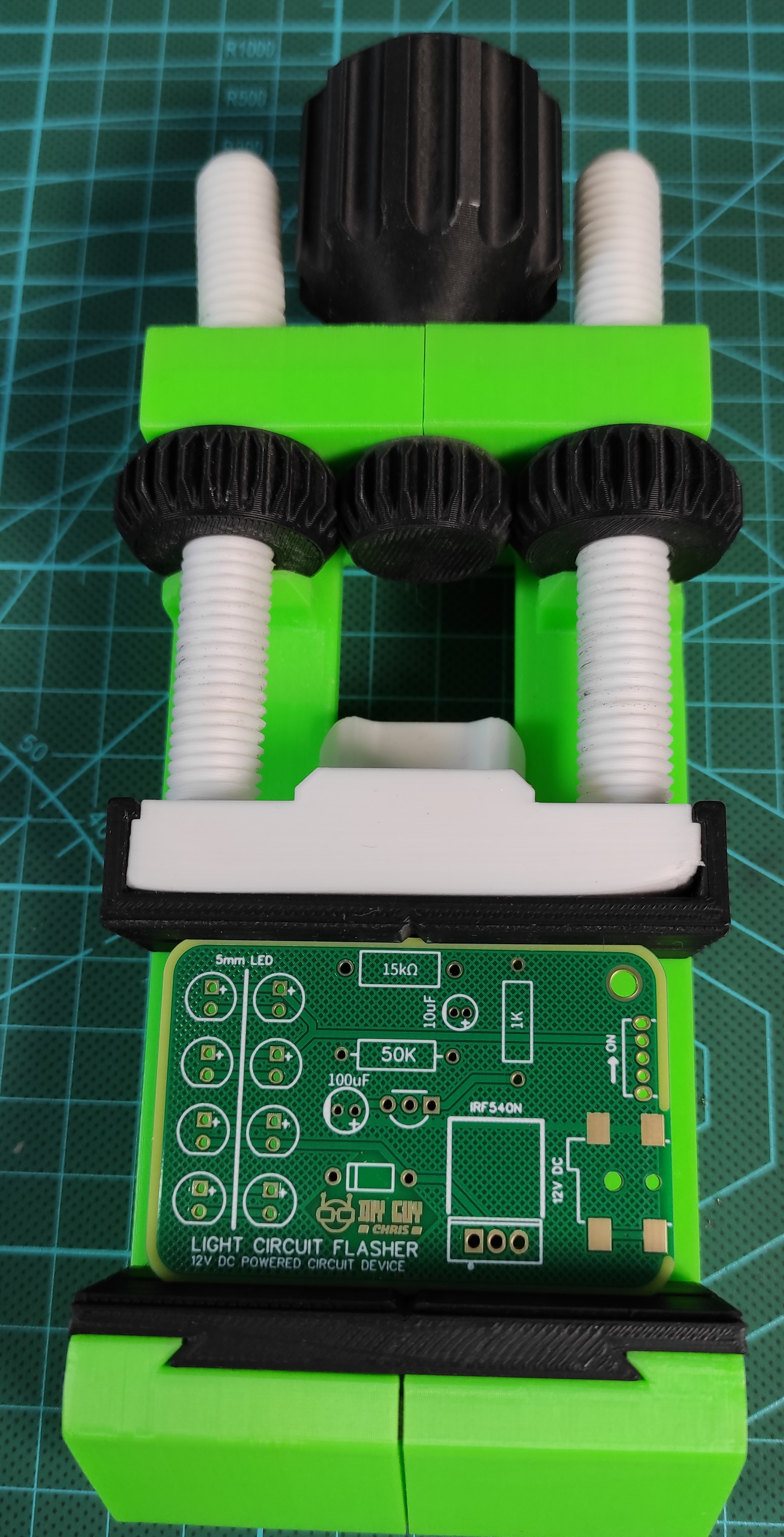
After getting the circuit board design ready, I exported its related GERBER files and uploaded them to JLCPCB to produce it, as soon as I got the Printed Circuit Boards delivered I then prepared my desktop for assembly by bringing the Vise circuit holder the tweezers, the solder iron and the solder core spool.
Make sure that you put each component to its placement on the board respectively following the circuit schematic, do not get confused especially with the resistors.
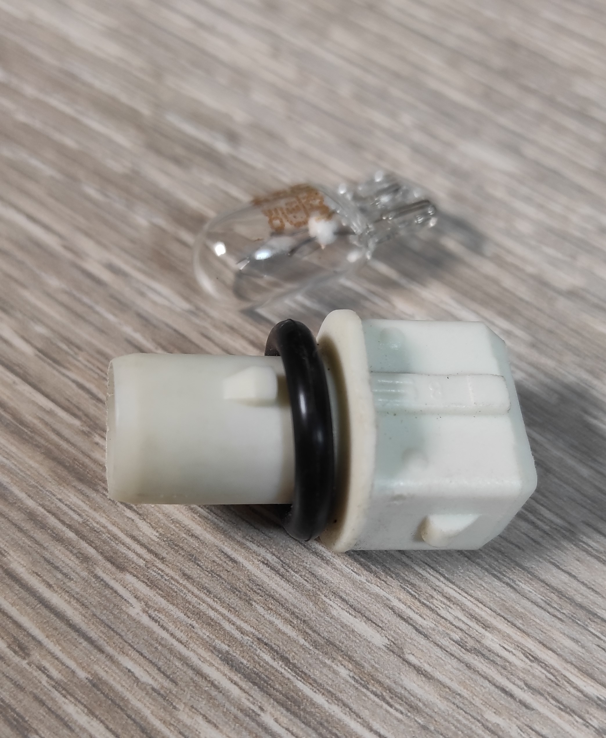
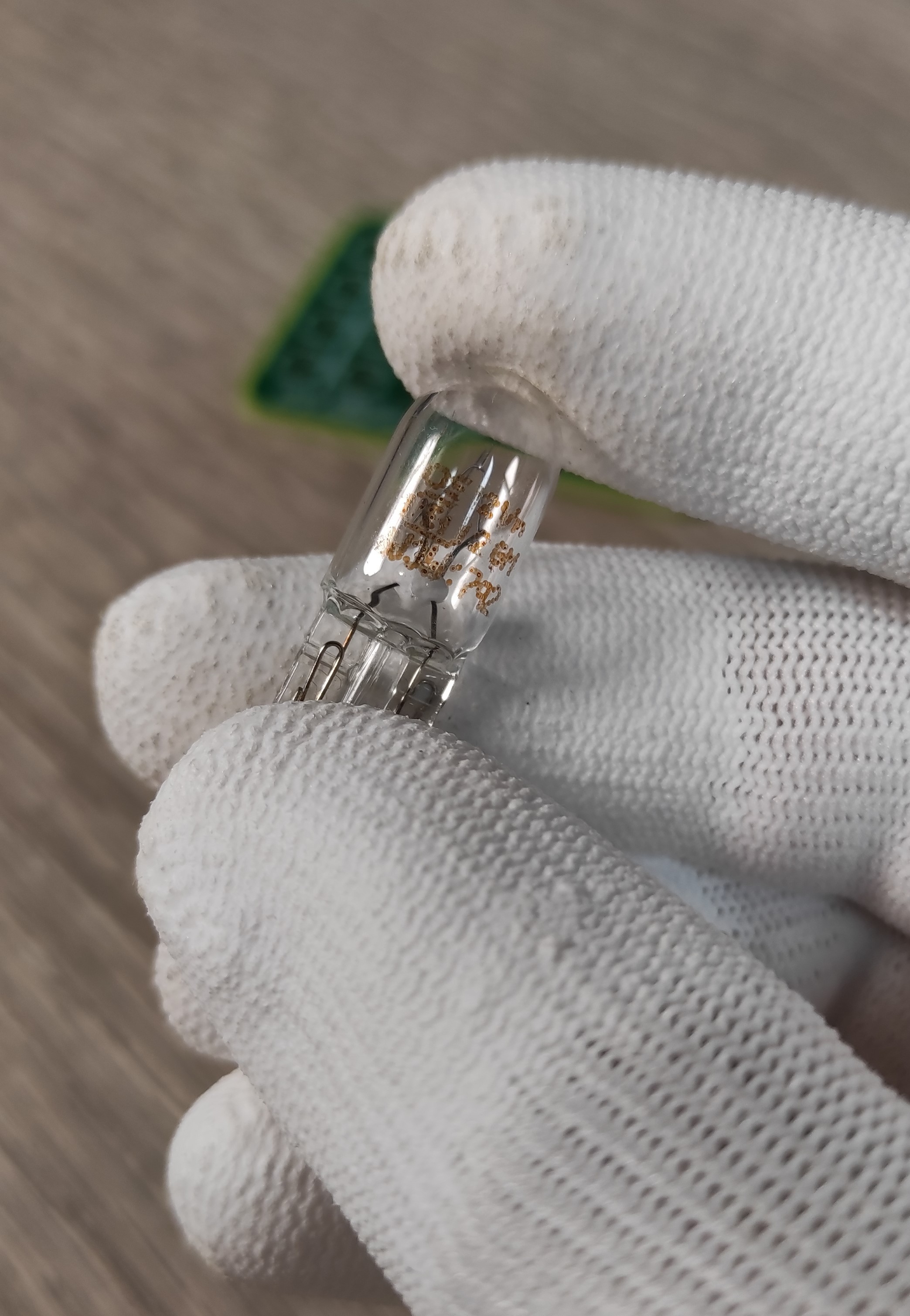
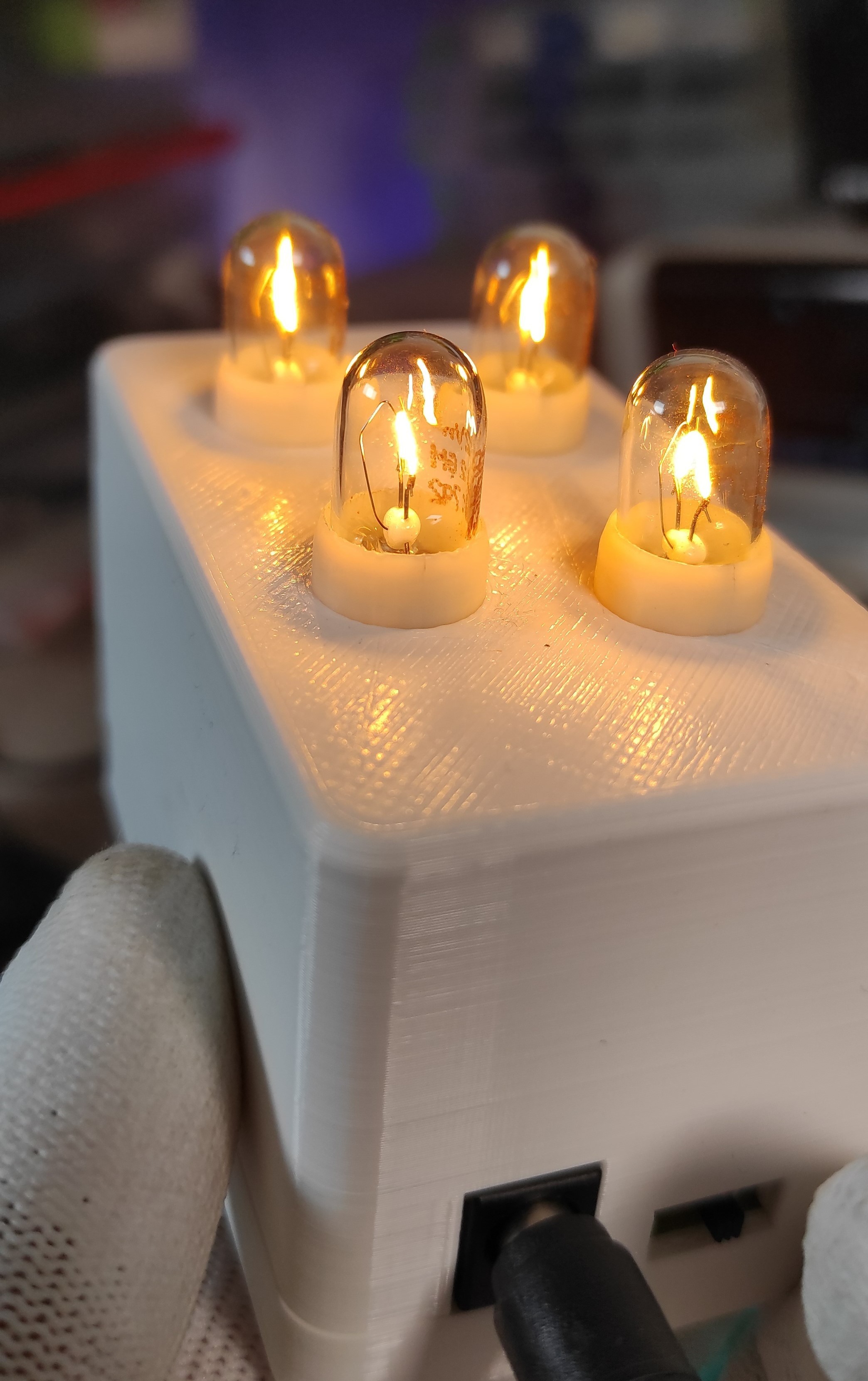
After soldering the components I then used a 12V Bulb housing and soldered its two wires (plus and mines) to the board output connection.
The circuit could handle up to 8 Bulbs, for my case I only used 4 Bulbs.
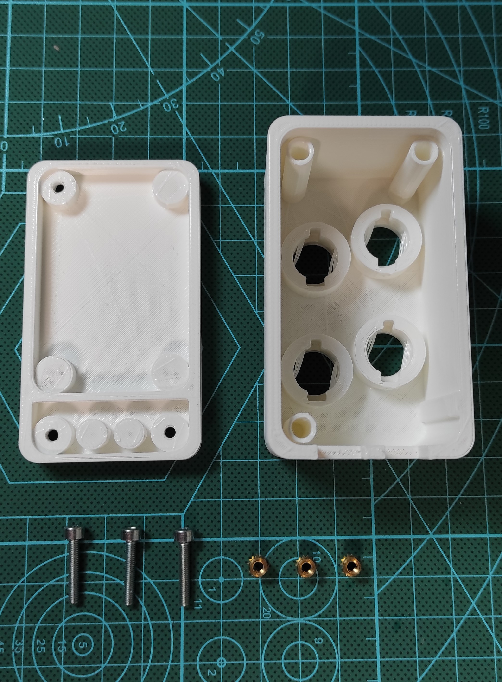
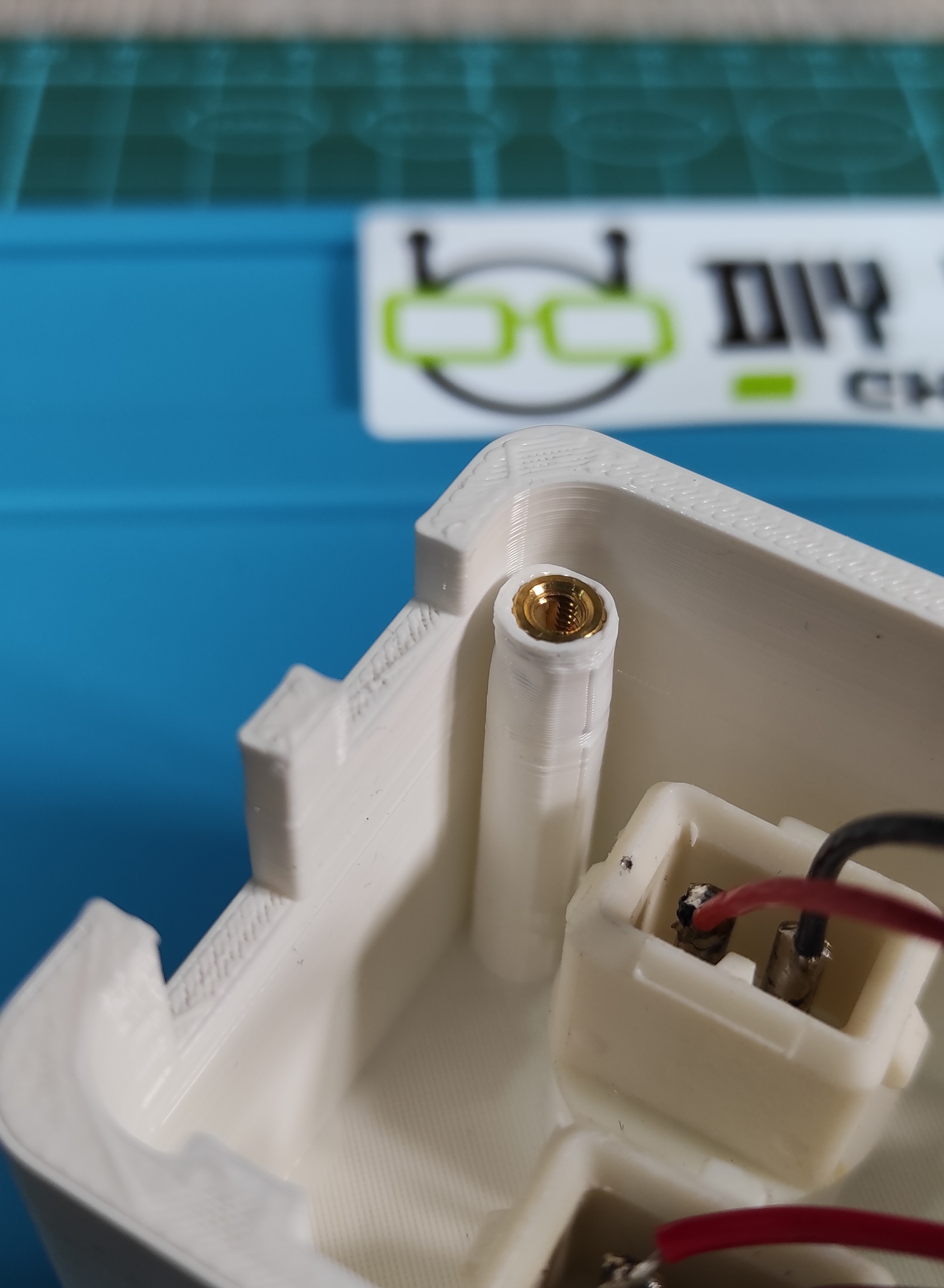
I designed a housing for my board and 3D printed it, then I used 3mm threaded inserts and 3mm screws to assemble the board to the housing.
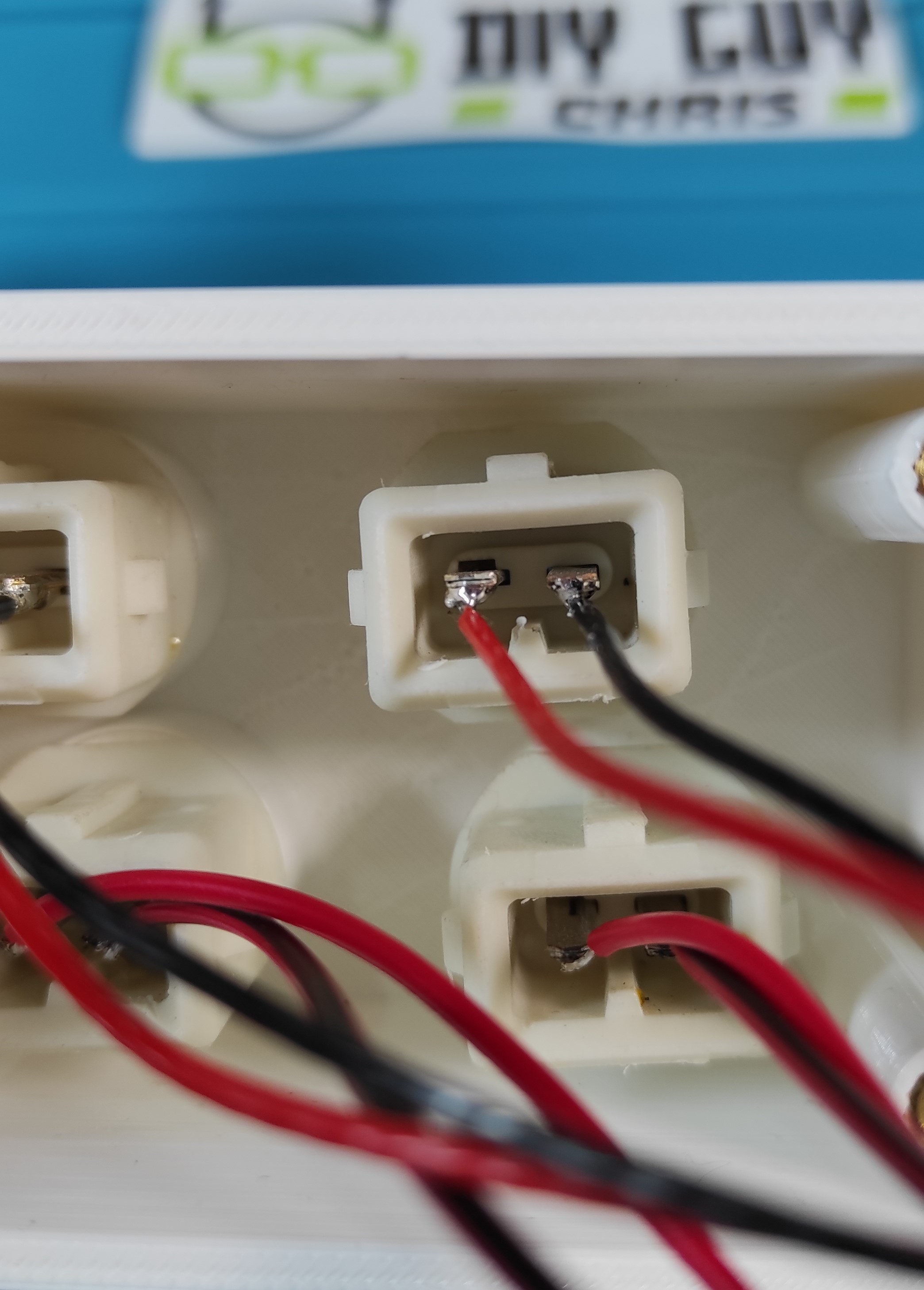
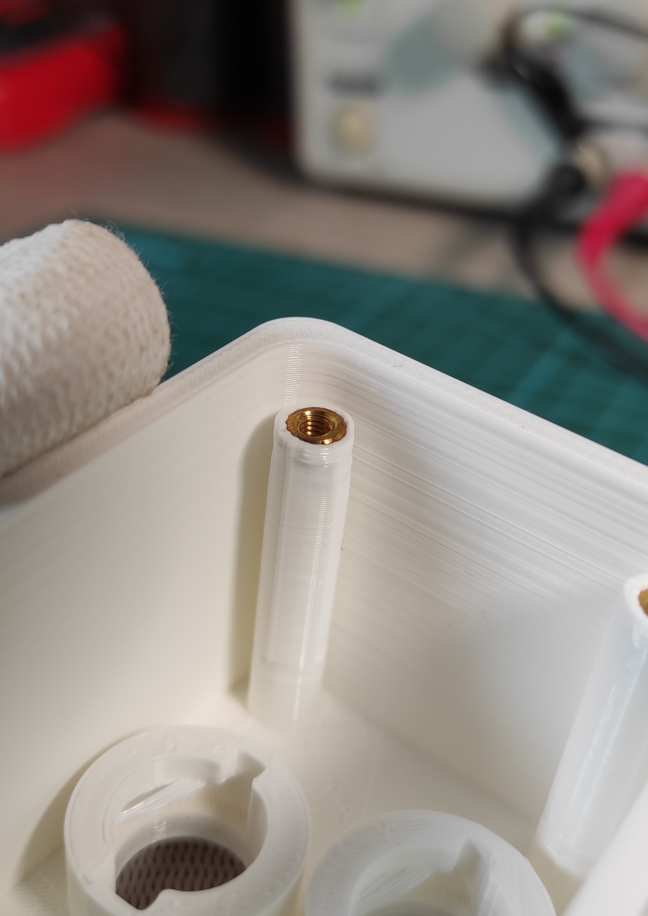
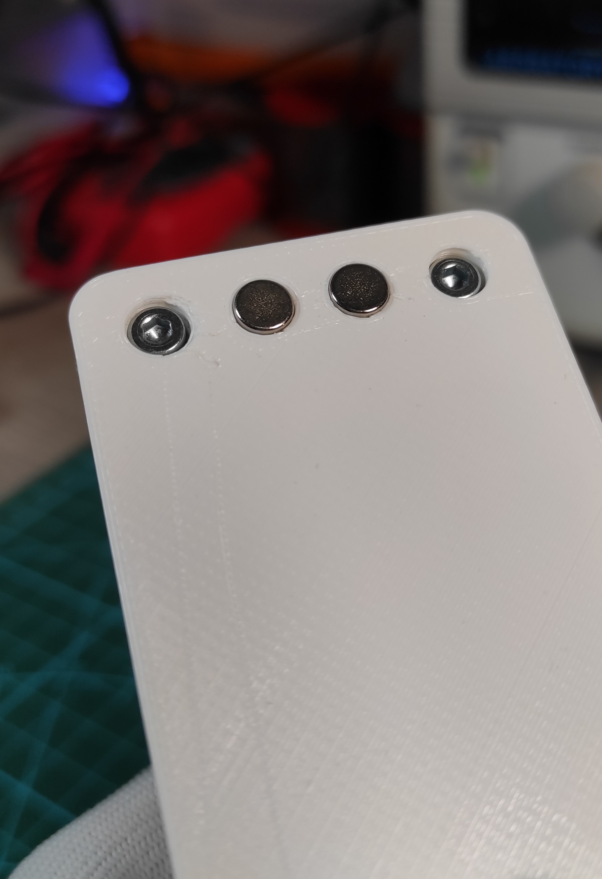
I prepared 4 slots in the housing design where I placed the Bulb housing and I also prepared two hole in the bottom side of the housing base where I placed two magnets to allow me easily attach the gadget to any metallic surface
After getting my circuit placed in the housing I powered it through the 12V DC power supply and the Bulbs start flashing.
This is it for today's project, maybe I will share another version of the same circuit based on SMD parts which makes the circuit smaller.
Please let me know your thoughts and suggestions in the comments section.
 MaBe42
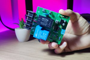
 Silícios Lab
 Kelly Heaton
 Tom Quartararo