 Tom Nardi
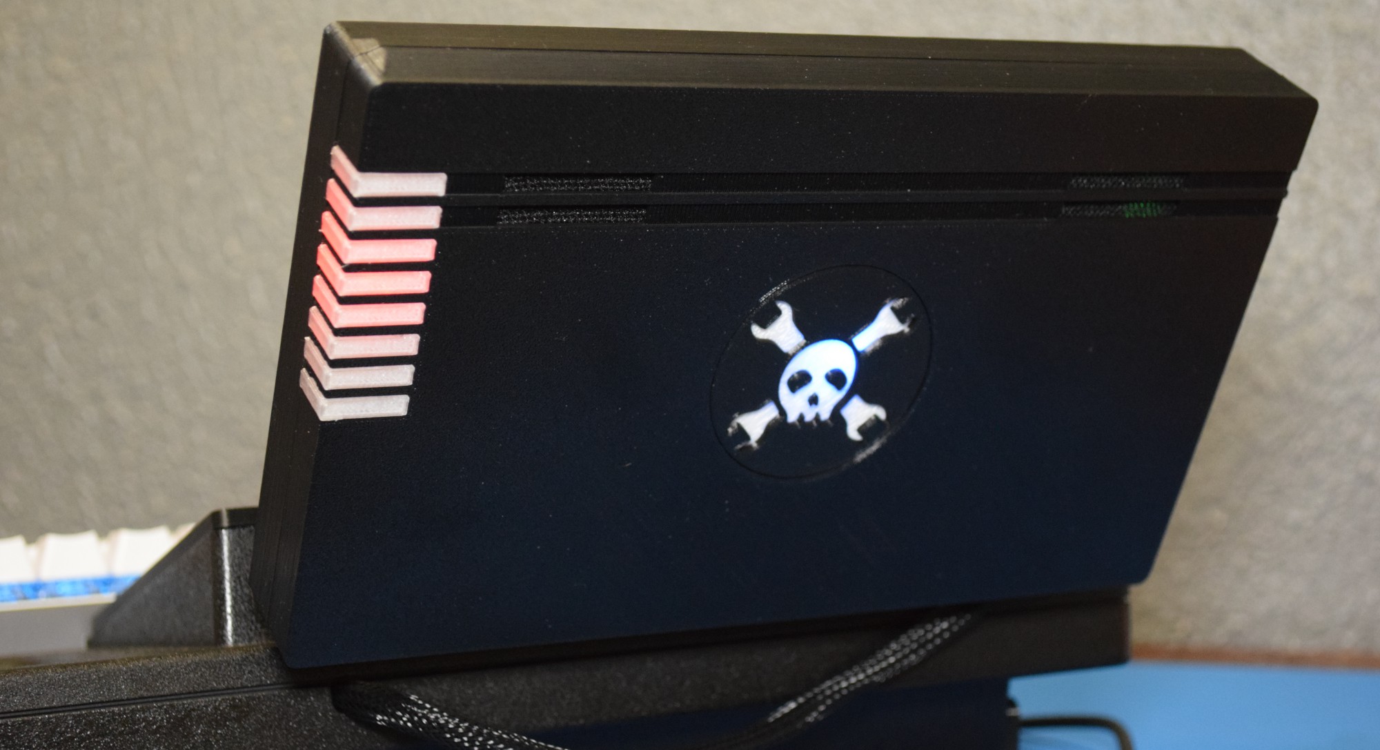
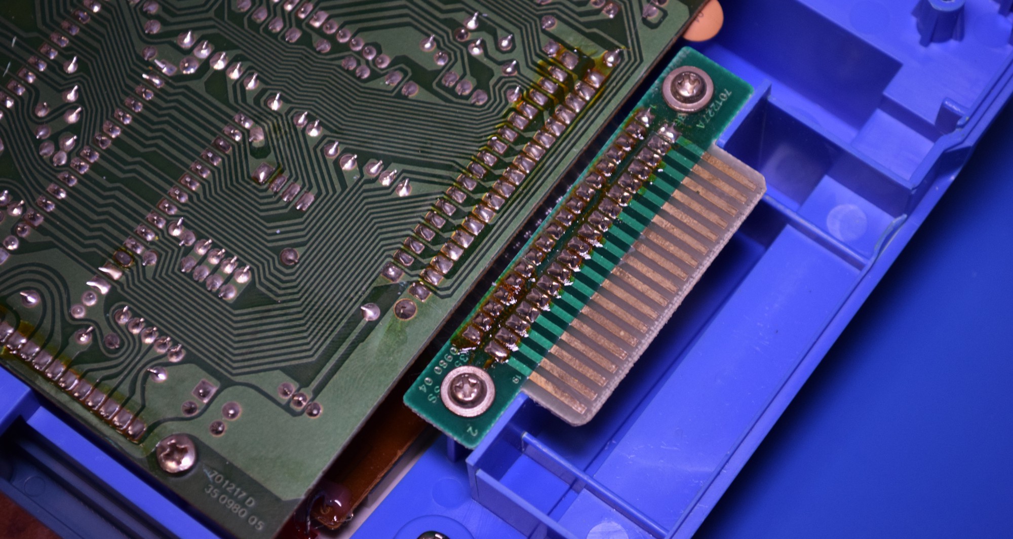
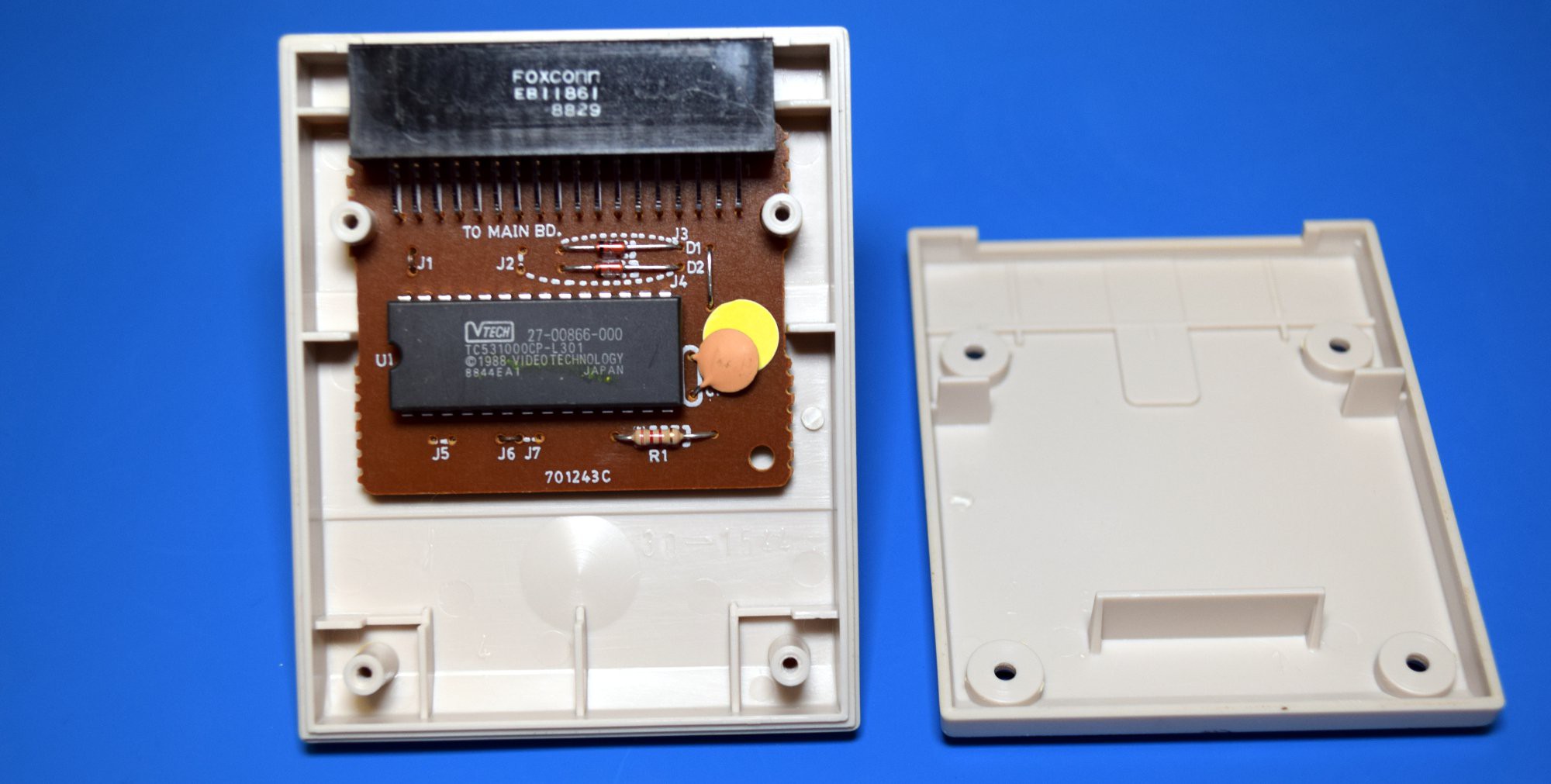
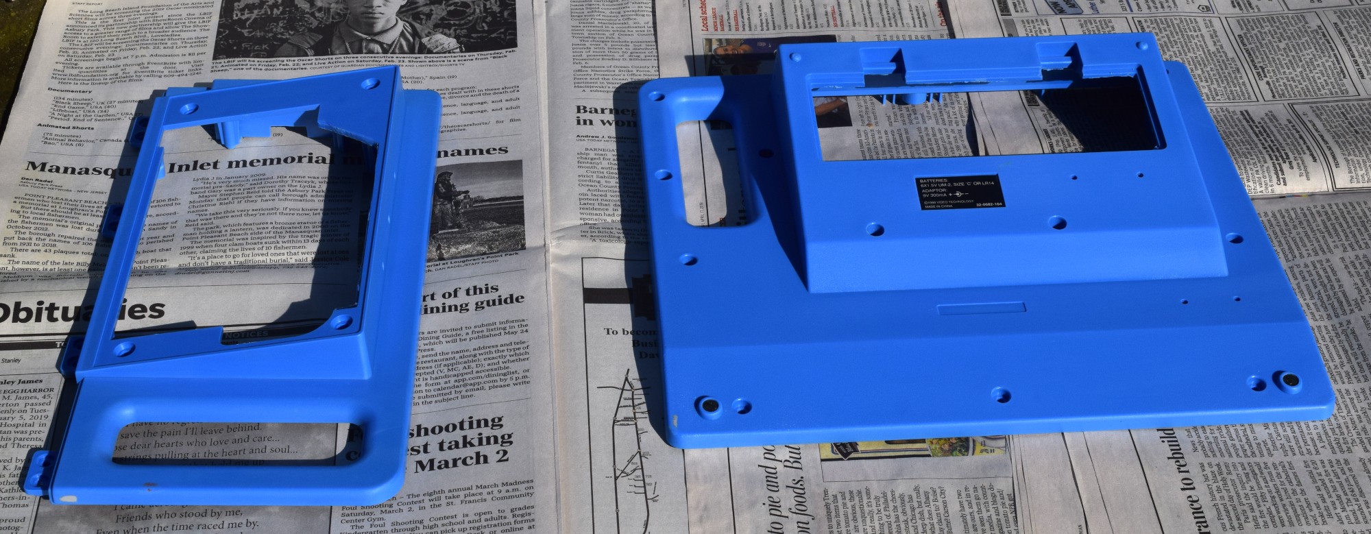
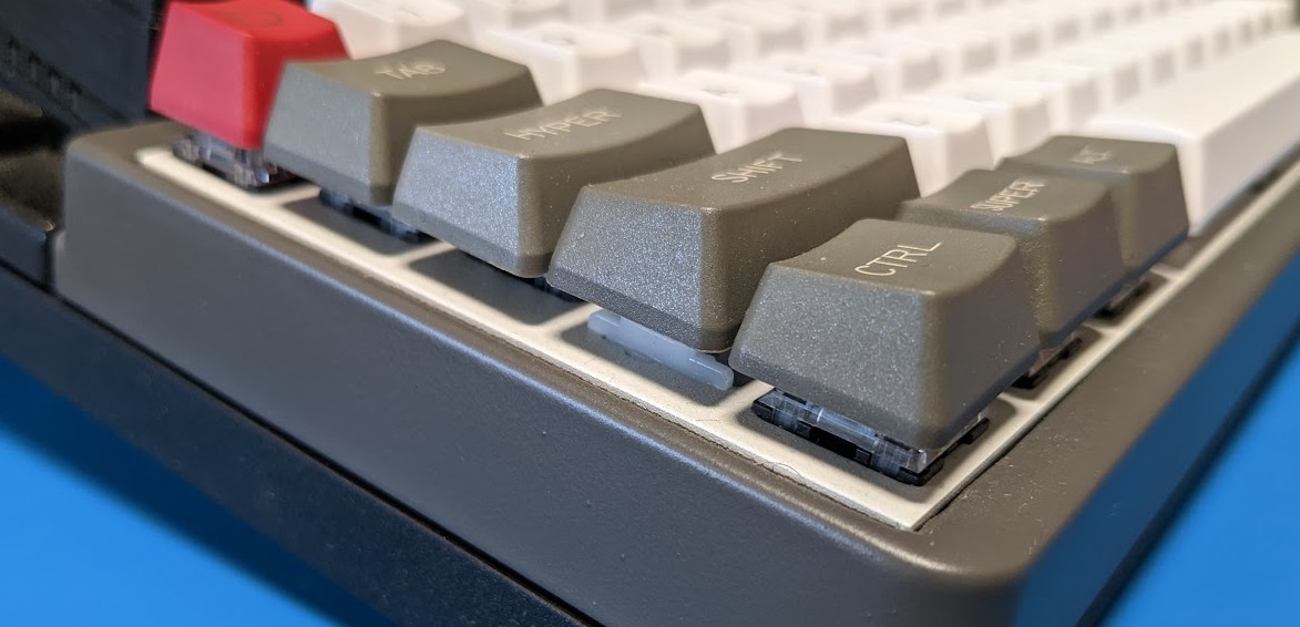
Everyone has a different reason for building their cyberdeck. For me, it was a desire to explore what computing could have been like if things had gone a little differently. What if concepts like expansion cartridges became more prevalent? What if computers kept that 80s bulk instead of becoming slimmer and lighter each year?
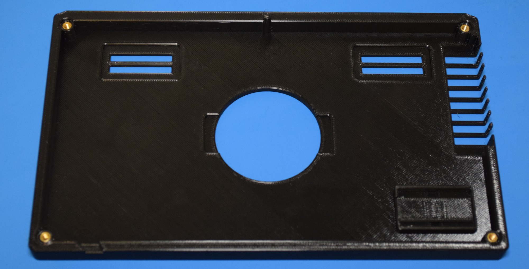
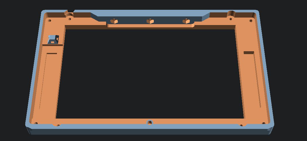
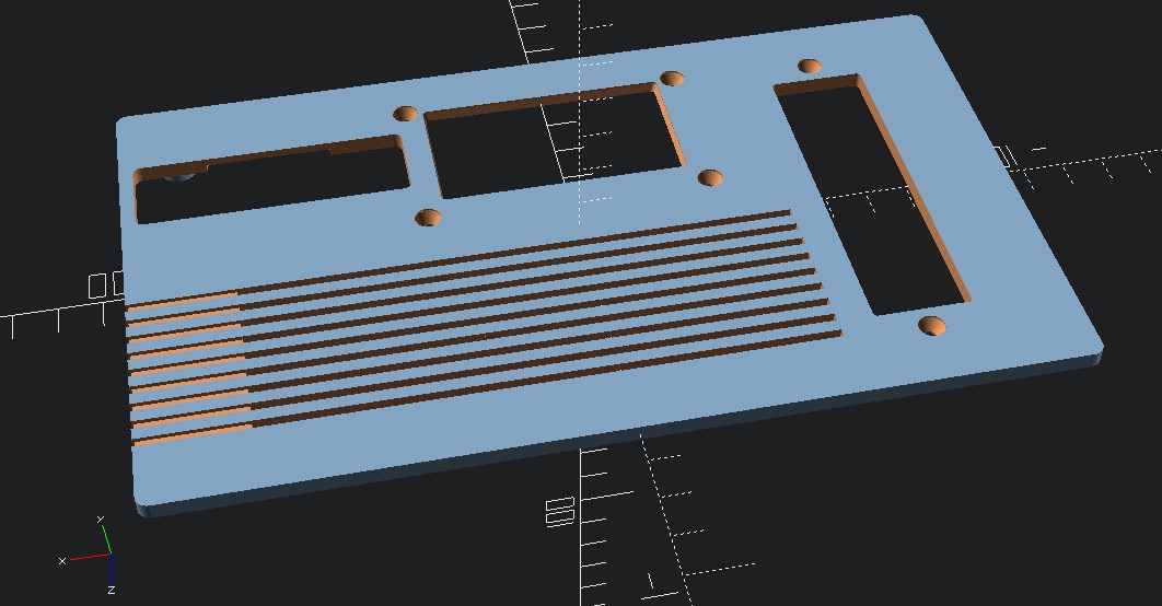
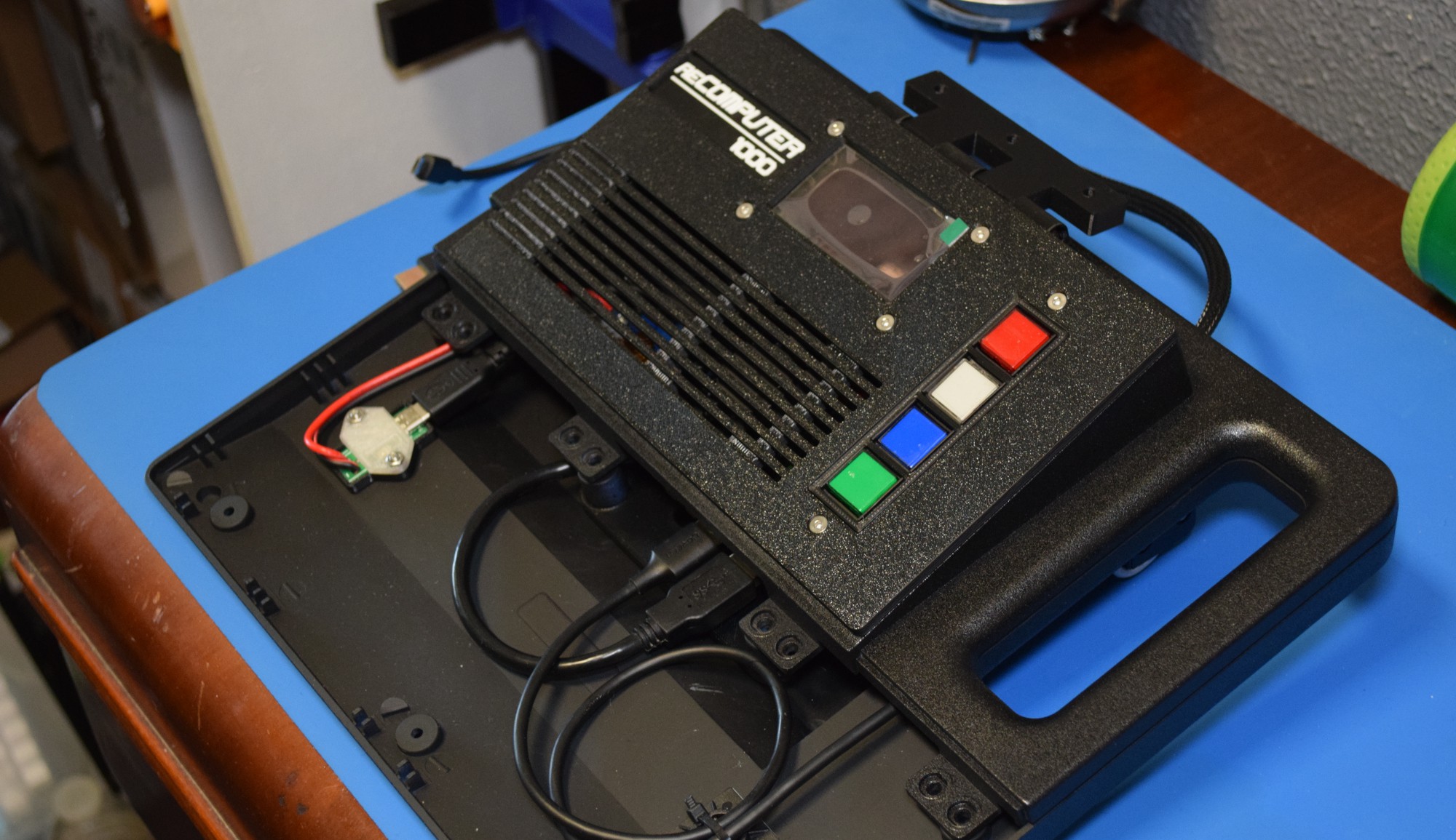
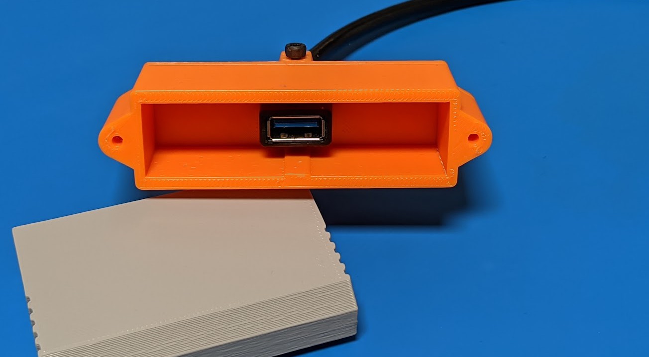
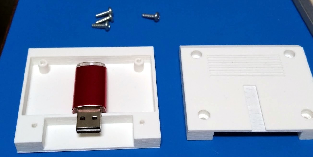
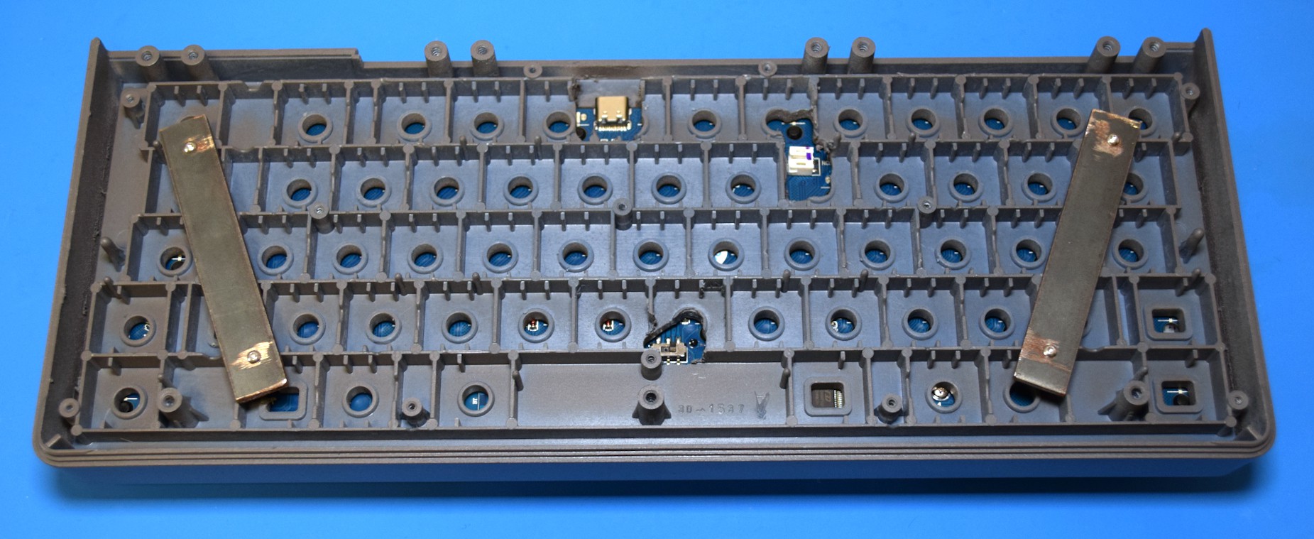
It was also important that my cyberdeck be easy to upgrade, maintain, and repair. We've all looked down at a half-disassembled laptop and wondered just what the hell the engineers behind it were thinking, and I wanted to create the opposite. Something you could pop open with just a few simple tools whenever you needed to get in there to fix or upgrade something.
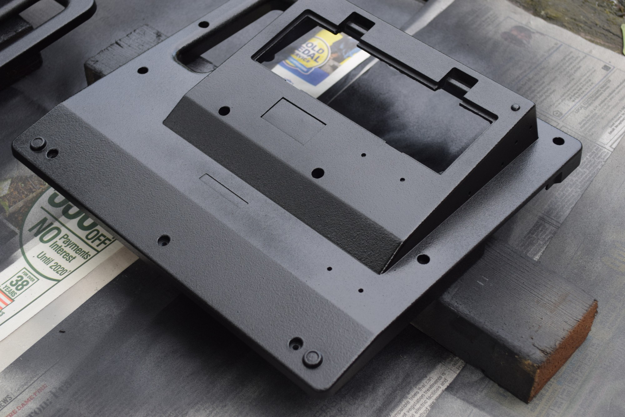
To that end, I've created a teardown video that I hope demonstrates not only the thought that went into putting the reComputer 1000 together -- but the thought that went into how you could take it apart again.


 Magic Robots
 Ari
Ari
 Retroplayer
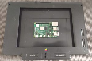
 Dan Jilek
Amazing Work. Also, visit https://apkranch.com/naruto-senki-mod-apk/.