 Martin Goodwell
The Lore
This is a little bit of Shadowrun-ish fan fiction to provide a background story for this cyberdeck.
Like every decker, every cyberdeck has a story. A past.
And this cyberdeck is no different.
It was born out of old, obsolete, and damaged parts. All of them used to be parts of different computers.
Regular computers. Used for playing games, for word processing, or for education.
As time passed, these computers became obsolete, and ended up in basements or attics, if they were lucky.
Others, which weren't, ended up in landfills and junkyards.
But of those who ended up in landfills, some where lucky, in that they were picked up by scavengers.
People who collected seemingly useful things and sold them.
This was before the Great Chip Shortage of the early twenties.
And when my grandfather - may his soul rest in peace - started collecting these pieces in these years of the chip shortage, he surely wasn't aware about what would finally become of them one day.
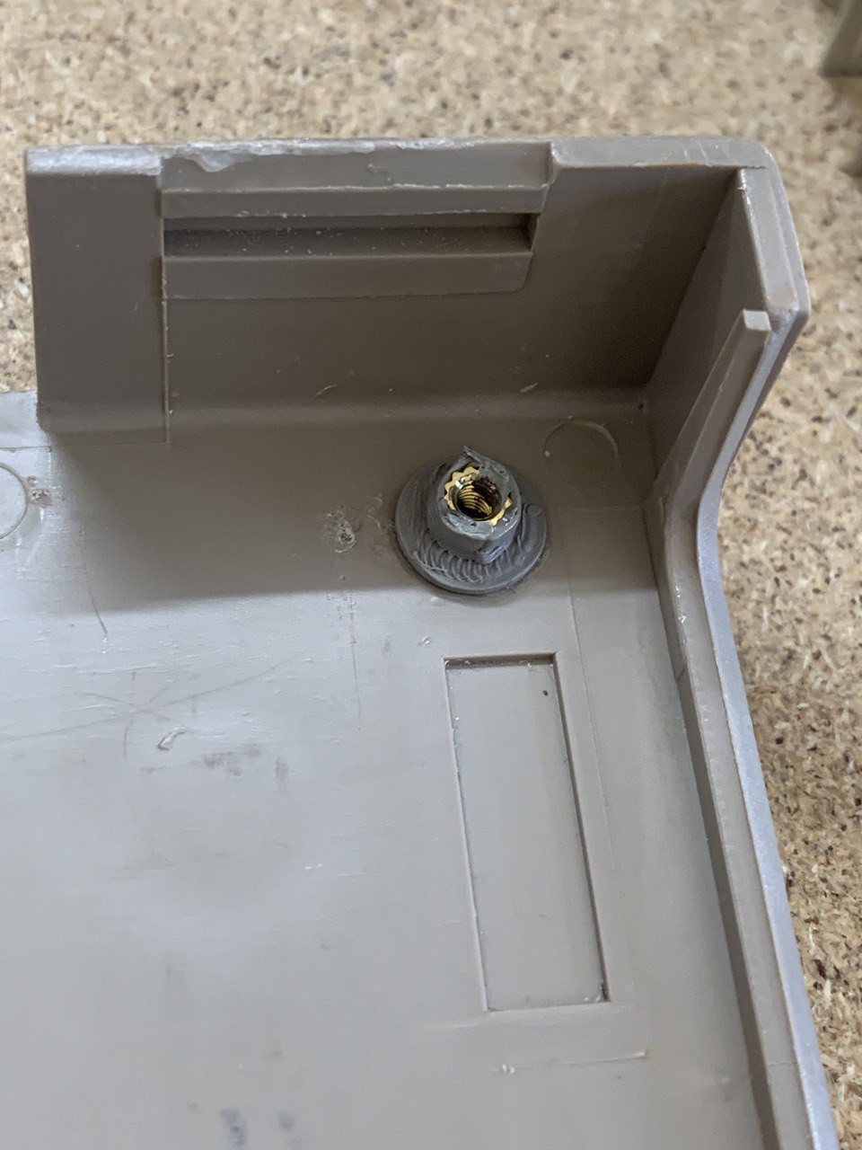
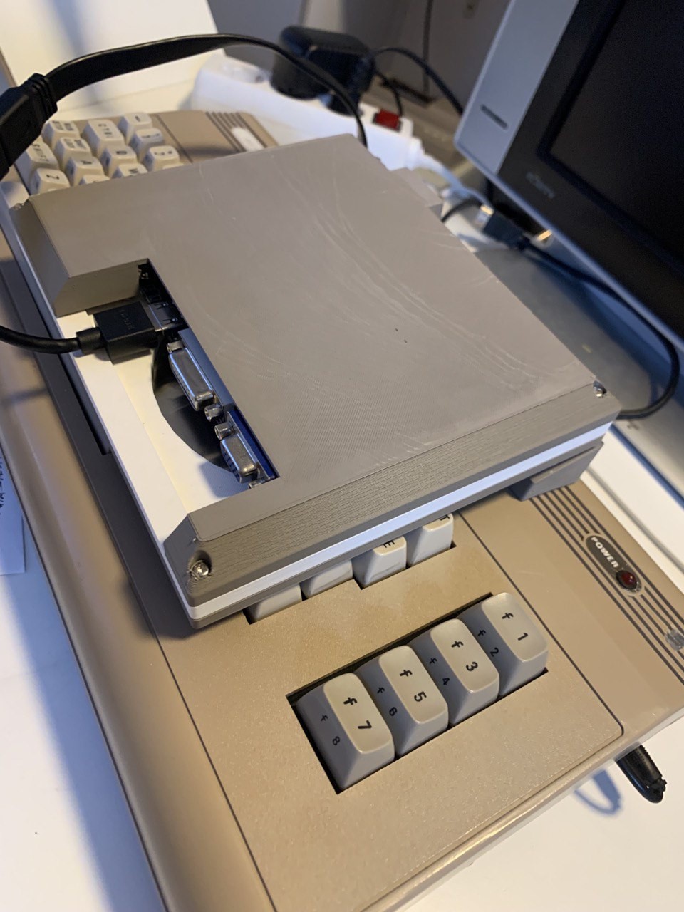
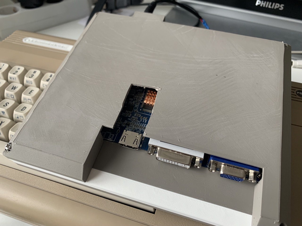
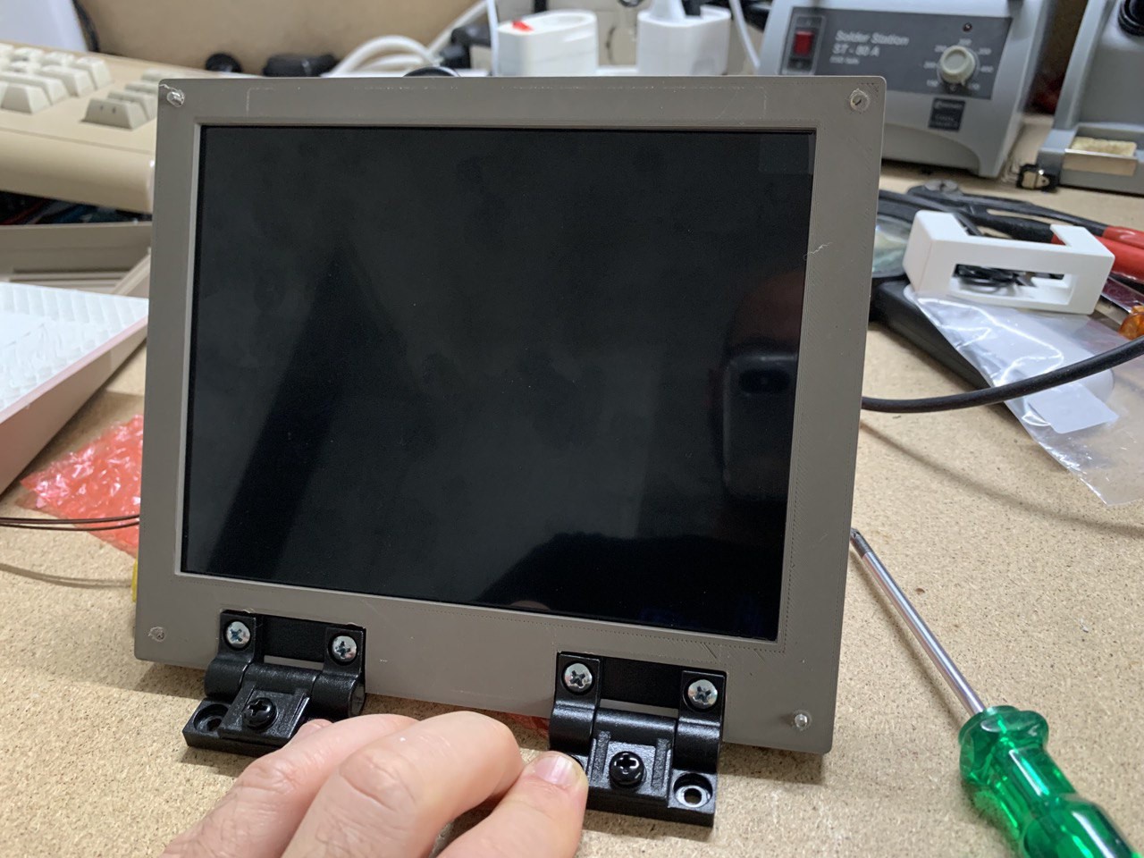
The case
He got the case from an online Marketplace. The price was way too high for what he got.
But still, somehow it was what he wanted. He didn't care about the money, he just knew
he wanted a case that's better off being modified and worked on, instead of waiting to be
scrapped.
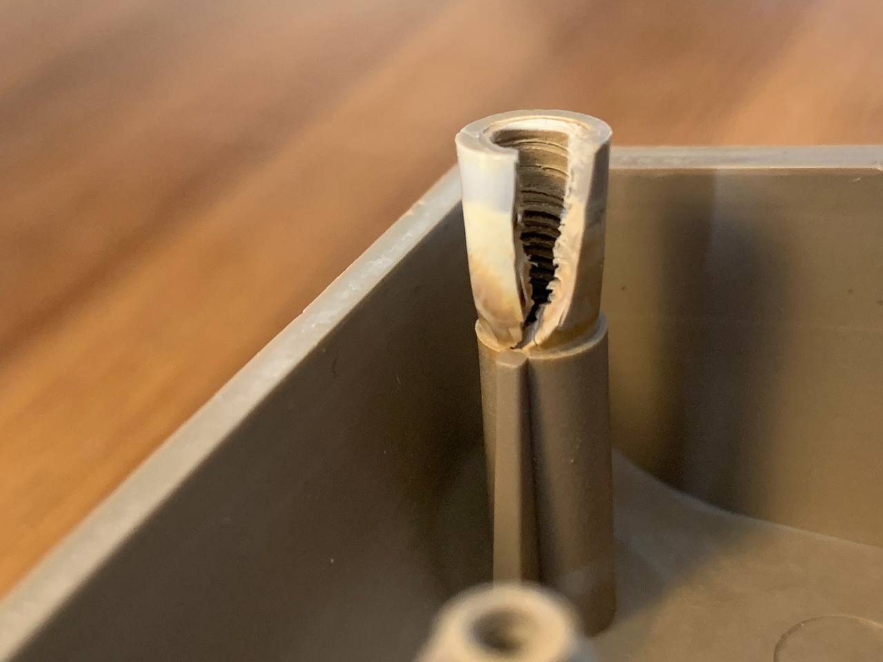
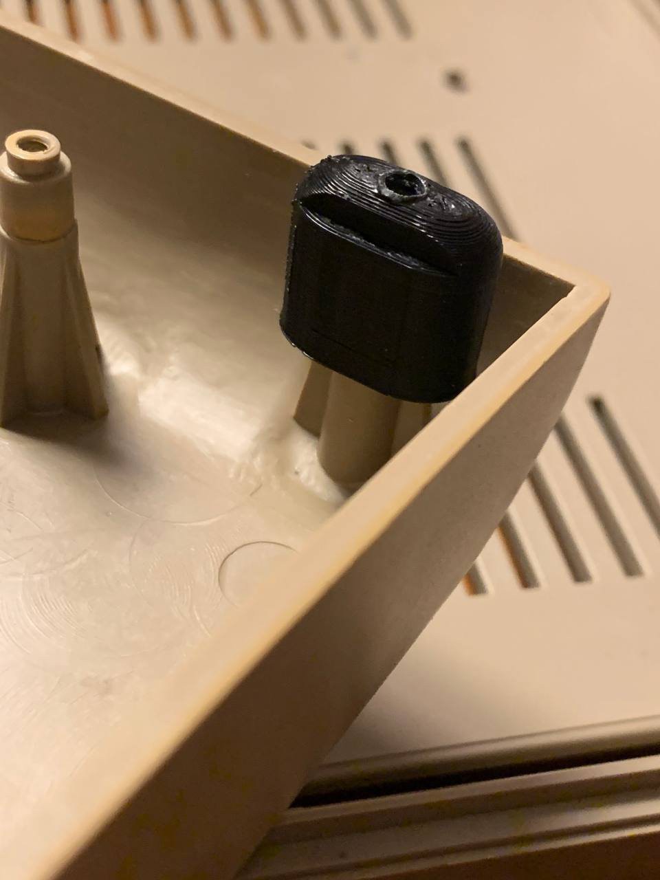
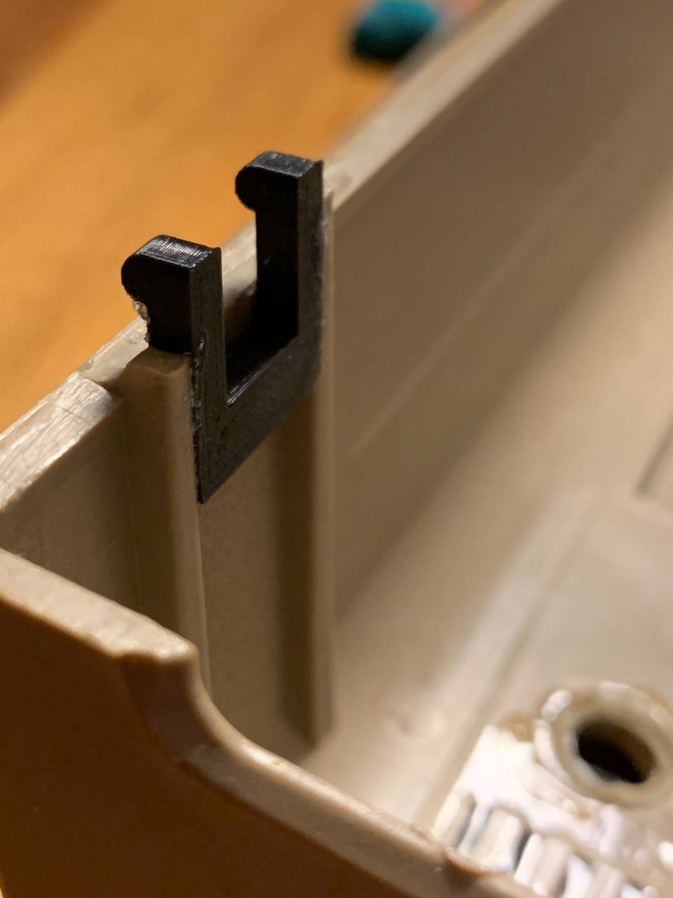
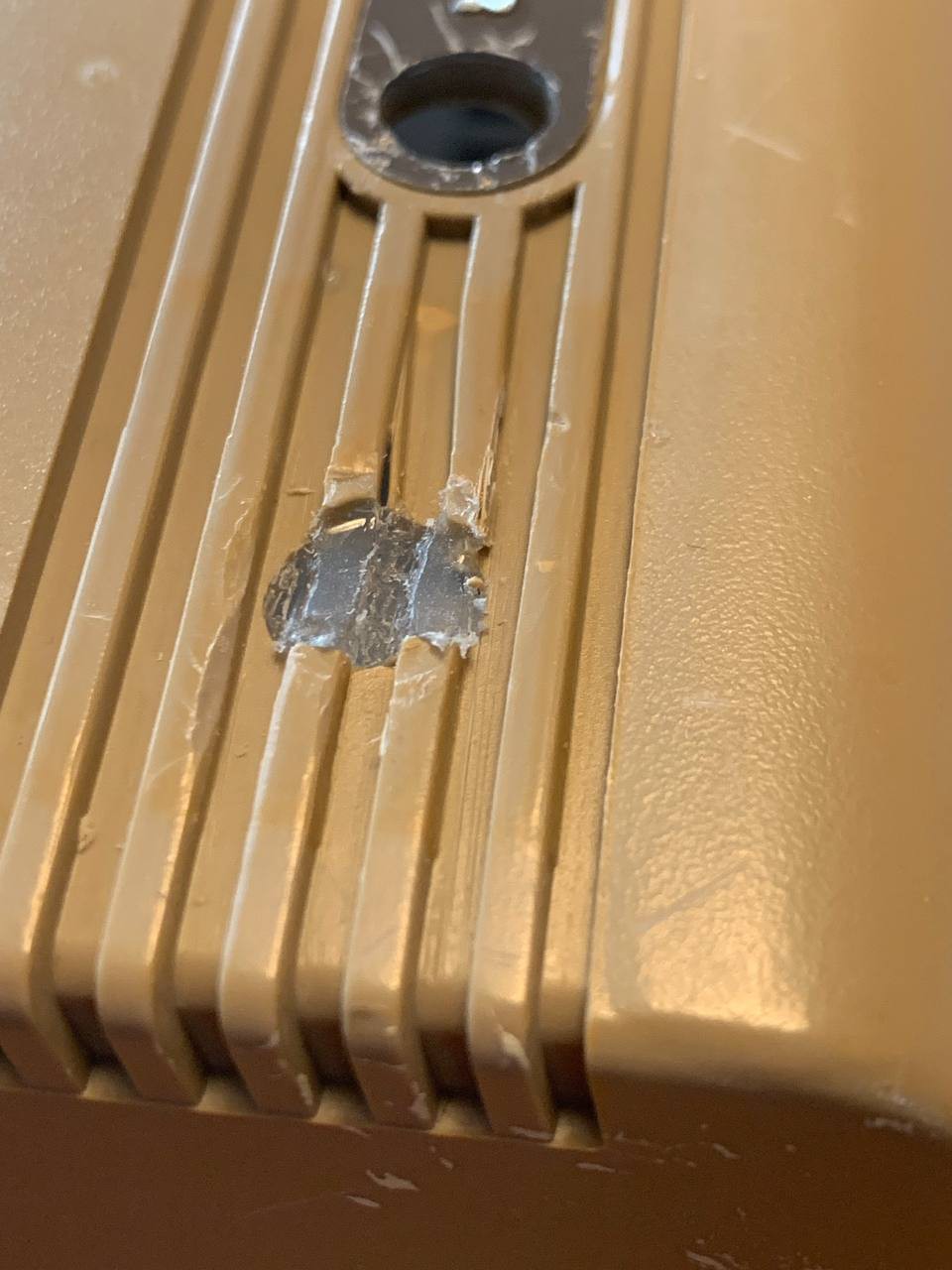
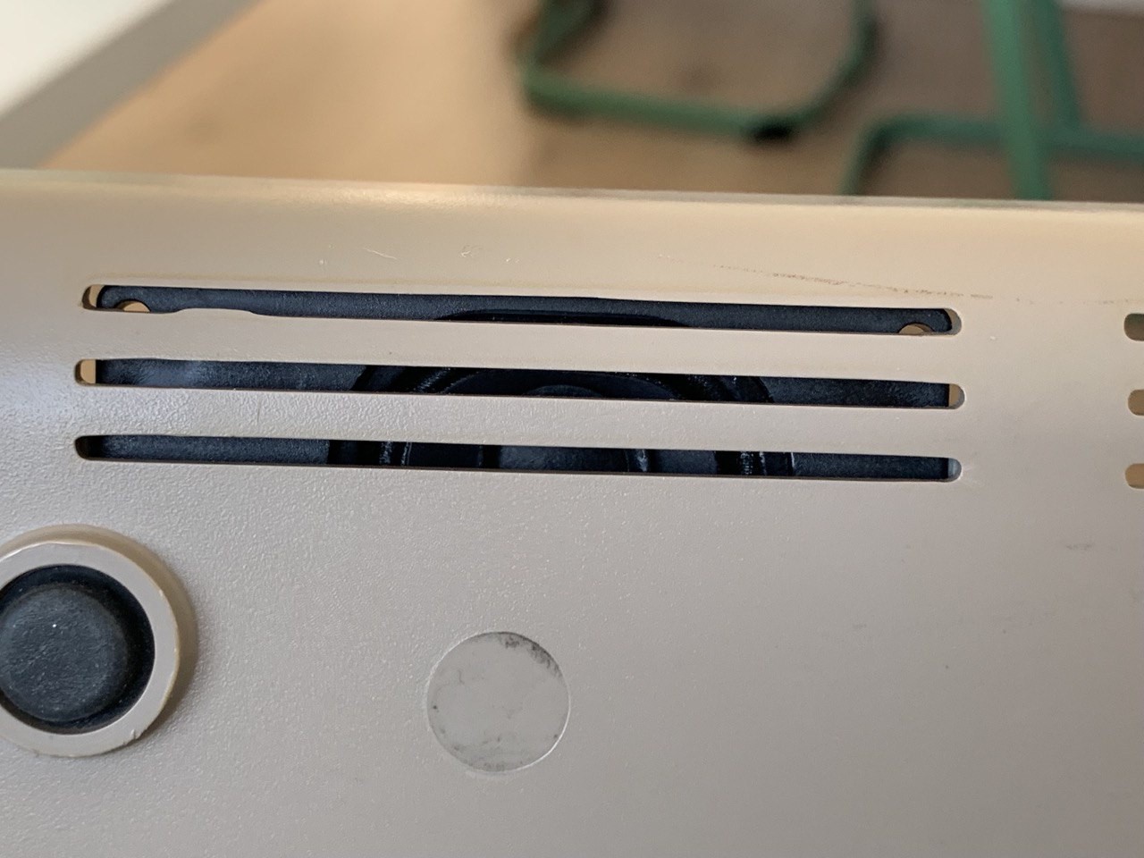
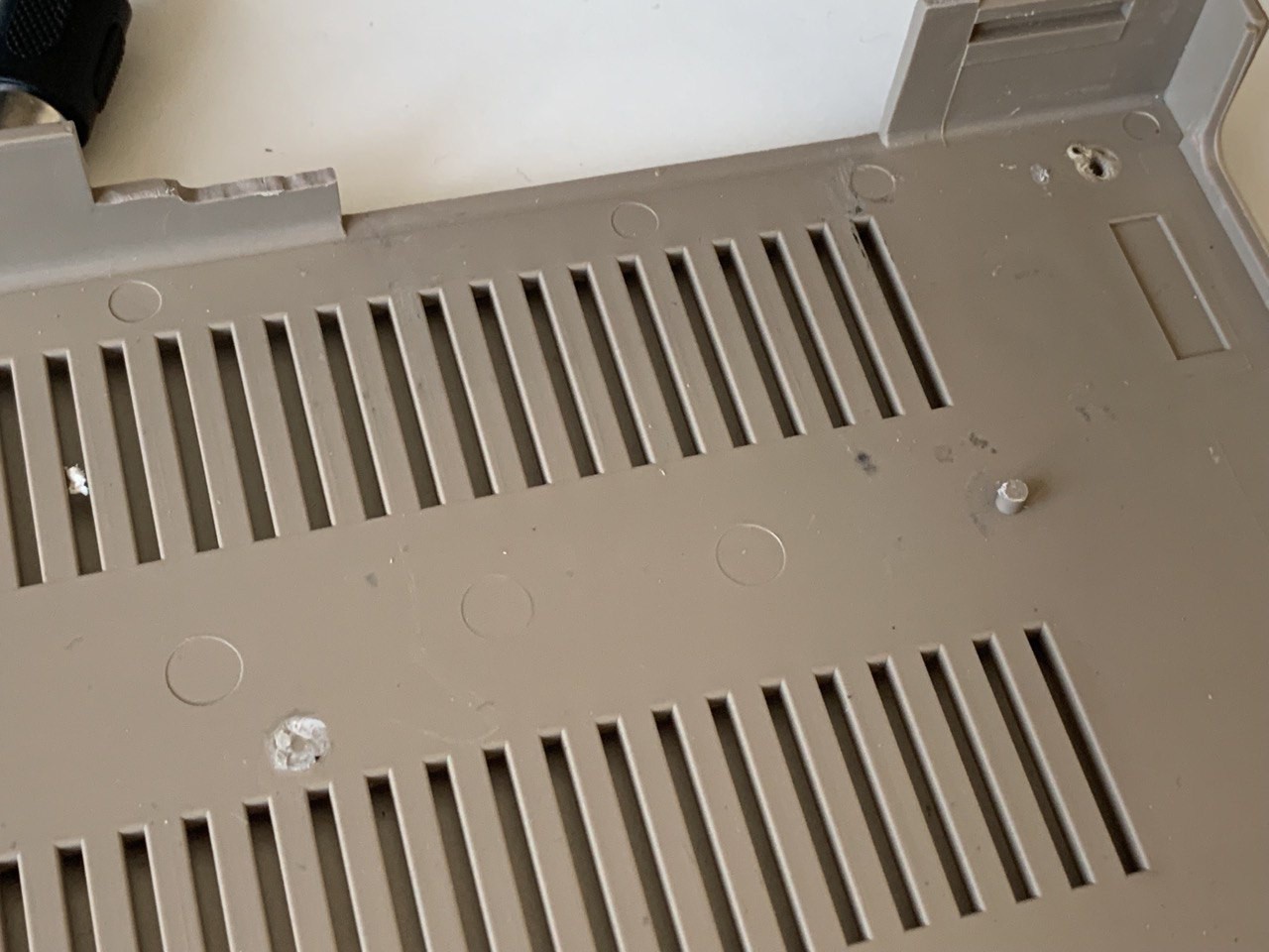
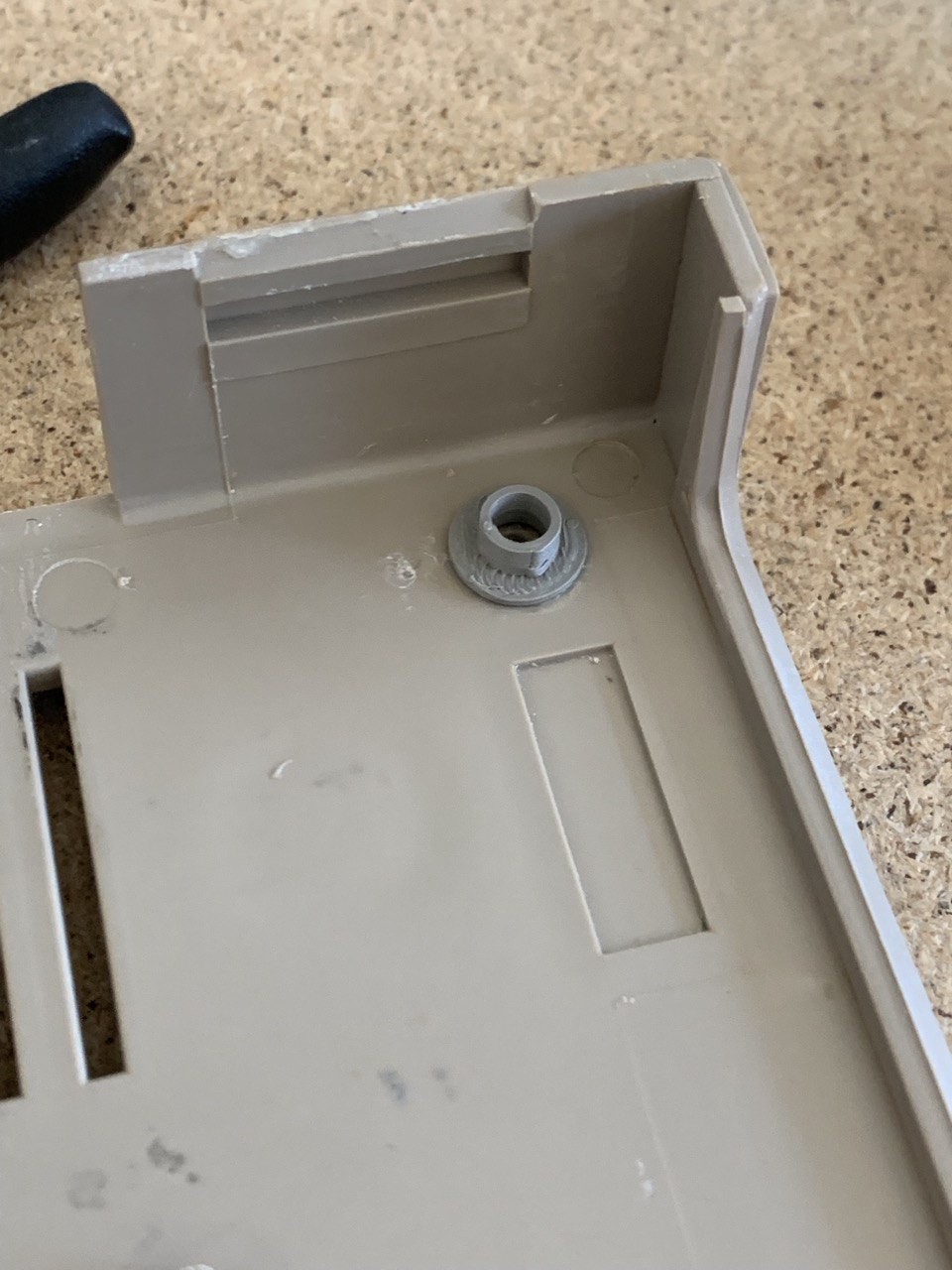
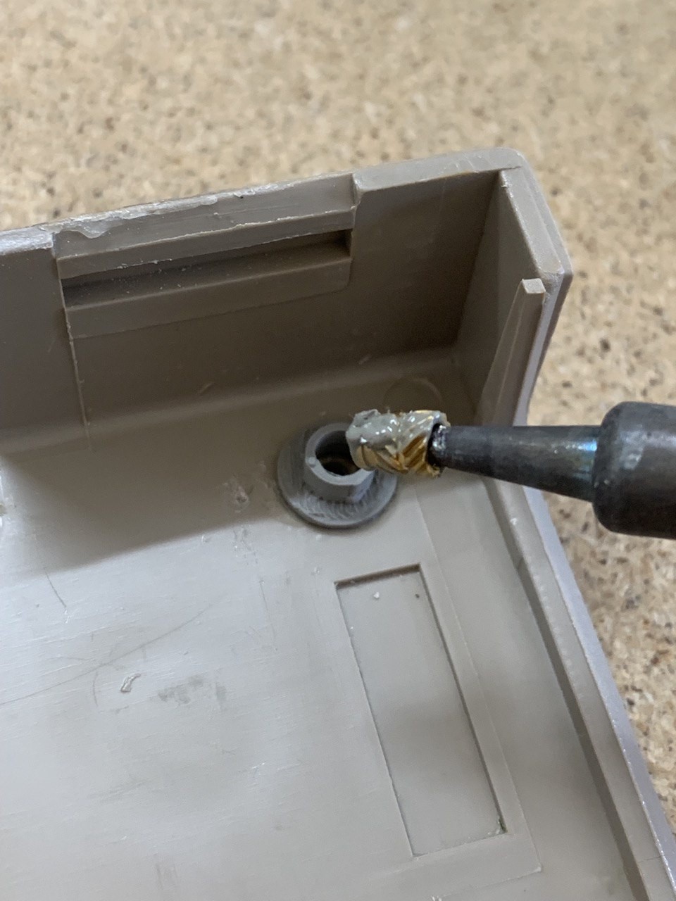
The case was in real bad shape, but my grandfather started filling the holes and replacing the broken pieces.
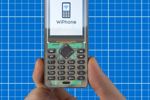
The keyboard
He got the keyboard from a friend in Vienna, a collector of weirdly modified computers. The keyboard itself wasn't modified, however. Still, it was in a place of all kinds of different and unique things, that were built by people who wanted something extraordinary.
With the keyboard in his hands, he knew that it was something unique that this keyboard would become an essential part of, too. And despite it's age, it was very well kept and taken care of. It was like brand new.
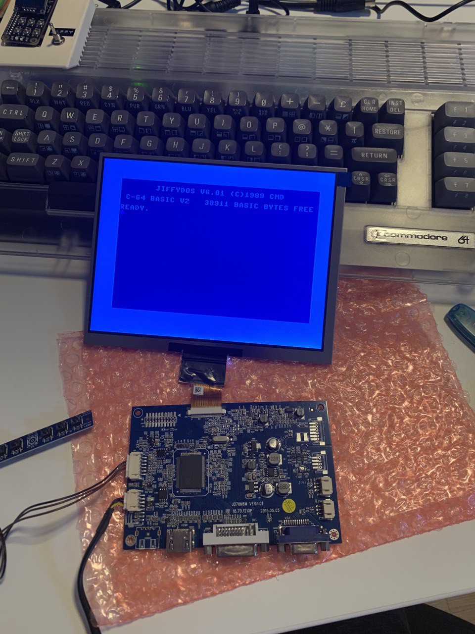
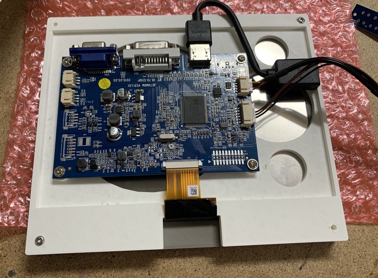
The mainboard
The component that would be home to all the electric components - the motherboard - is the odd thing in between all these old and obsolete parts.
It was made for all the old chips, but all the glue logic that connects these chips was a brand new design. Not relying on single parts that can fail, but on high-end FPGA technology.
This would be far more resilient to any external influence. On the downside, if it was broken, it was broken for good.
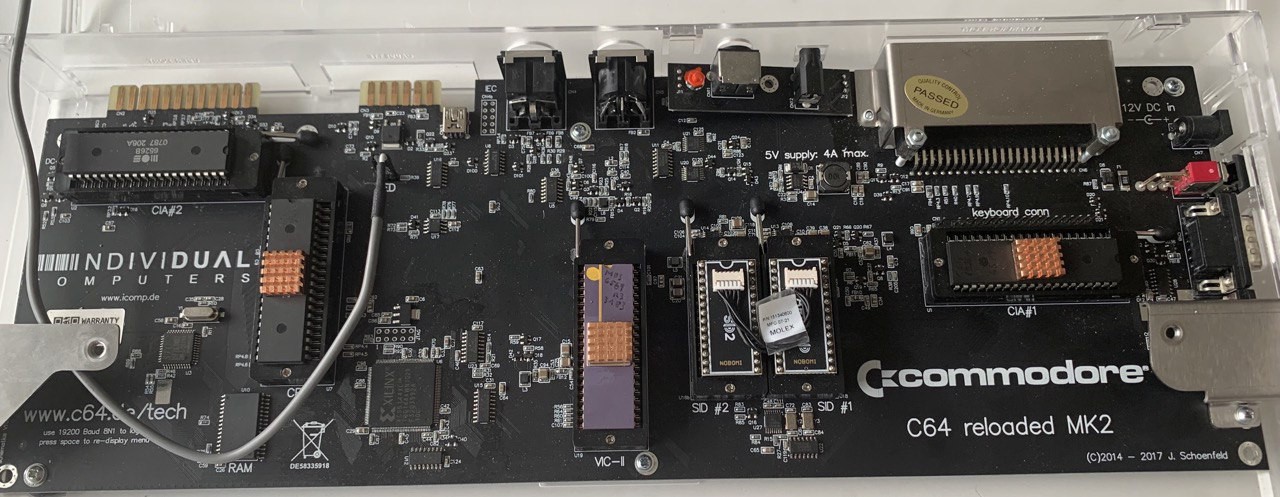
There was no single logic chip that you could replace, the whole mainboard would be gone and need to be replaced.
But one other advantage - and maybe the biggest one - was, that this allowed for much simpler power supply.
12V DC only, instead of 9V AC and 5V DC. This would make everything else much easier.
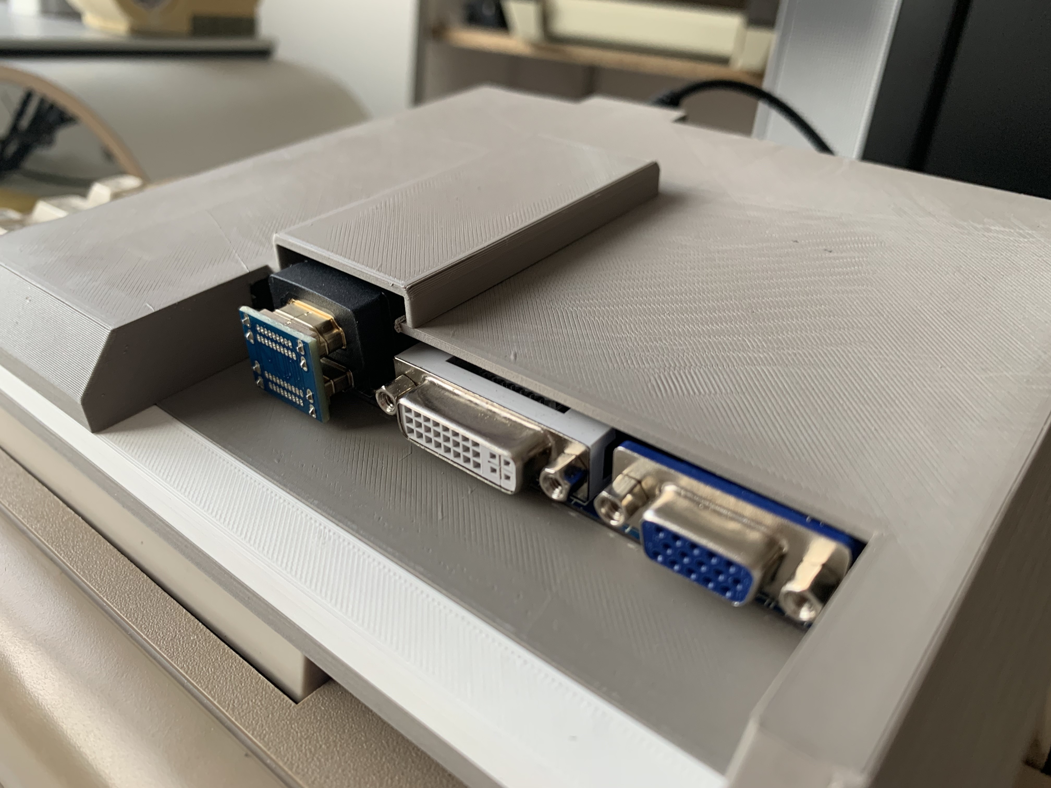
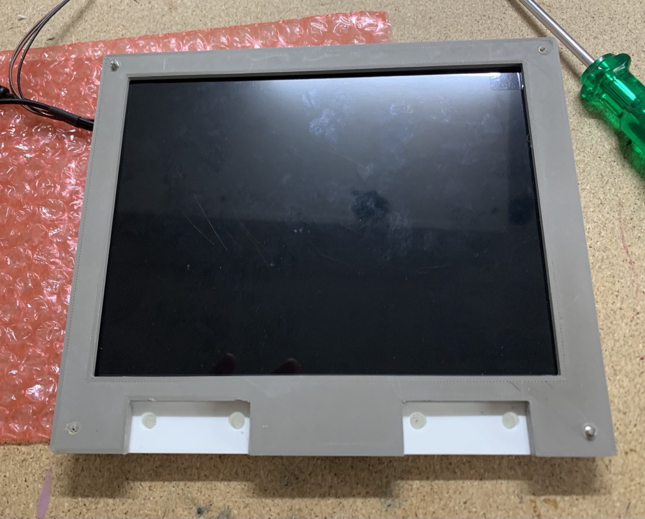
The other mainboard
My grandfather had another "new" mainboard at hand as well. This one was a true all-in-one solution in that it needed no additional chips. And it was able to mimic peripherals as well.
Still, it was made to fit the original case, so from the outside you wouldn't necessarily recognize what was inside.
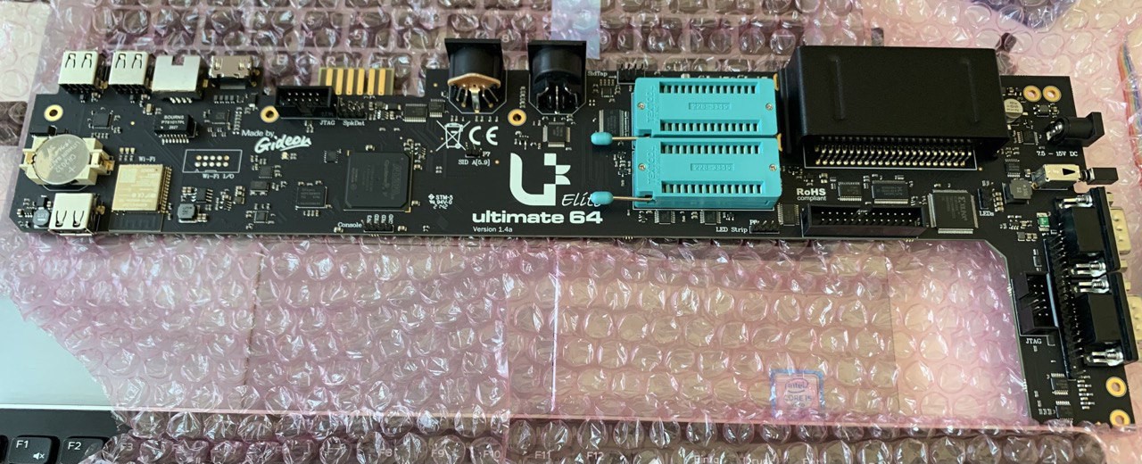
I'm not yet sure which board to use. But if one doesn't work, I'll just try the other. And maybe both will work. If so, I'm convinced that each one will give the cyberdeck it's own unique personality.
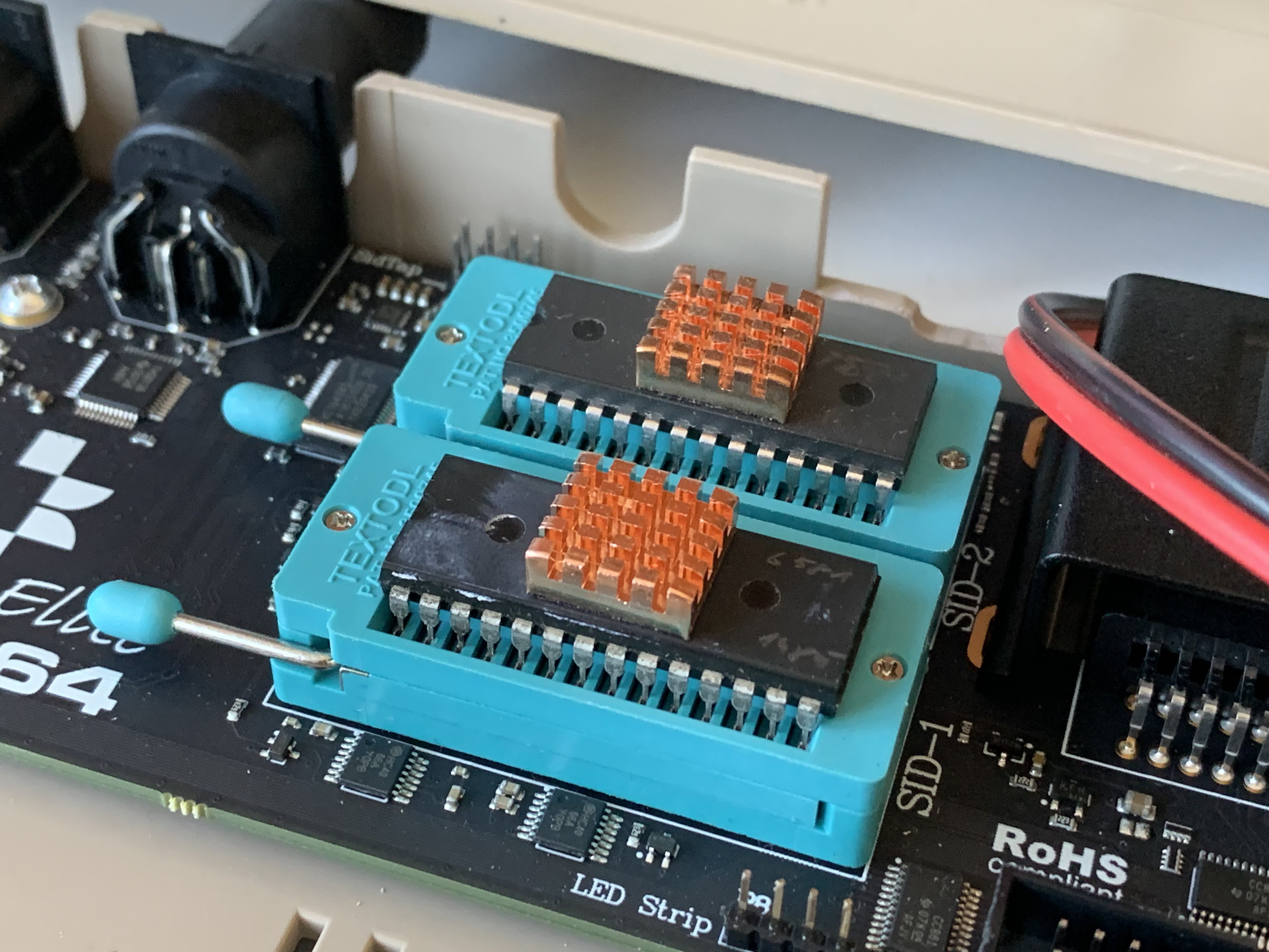
The chips
Processor, Video chip, Sound chip, and interface chips. All these came from dealers around the place. Hand picked, for sure, but still parts that
have been taken out of their original homes. Very often, ruthless corporate suits would cannibalize otherwise good devices just for the parts.
It was obsolete hardware anyways, so why should anyone care if a fully working computer was sitting in a basement, or if the parts were sold for good money?
I can't tell you all the stories behind these components, as I haven't been there when they happened. Heck, I wasn't even born back then.
However, I'll take the parts that my grandfather has collected so painstakingly, and I'll see if I can make something good, something new out of them.
What good is a 1 MHz cyberdeck, you ask?
Rumor has it, that with The Awakening in 2011, not...
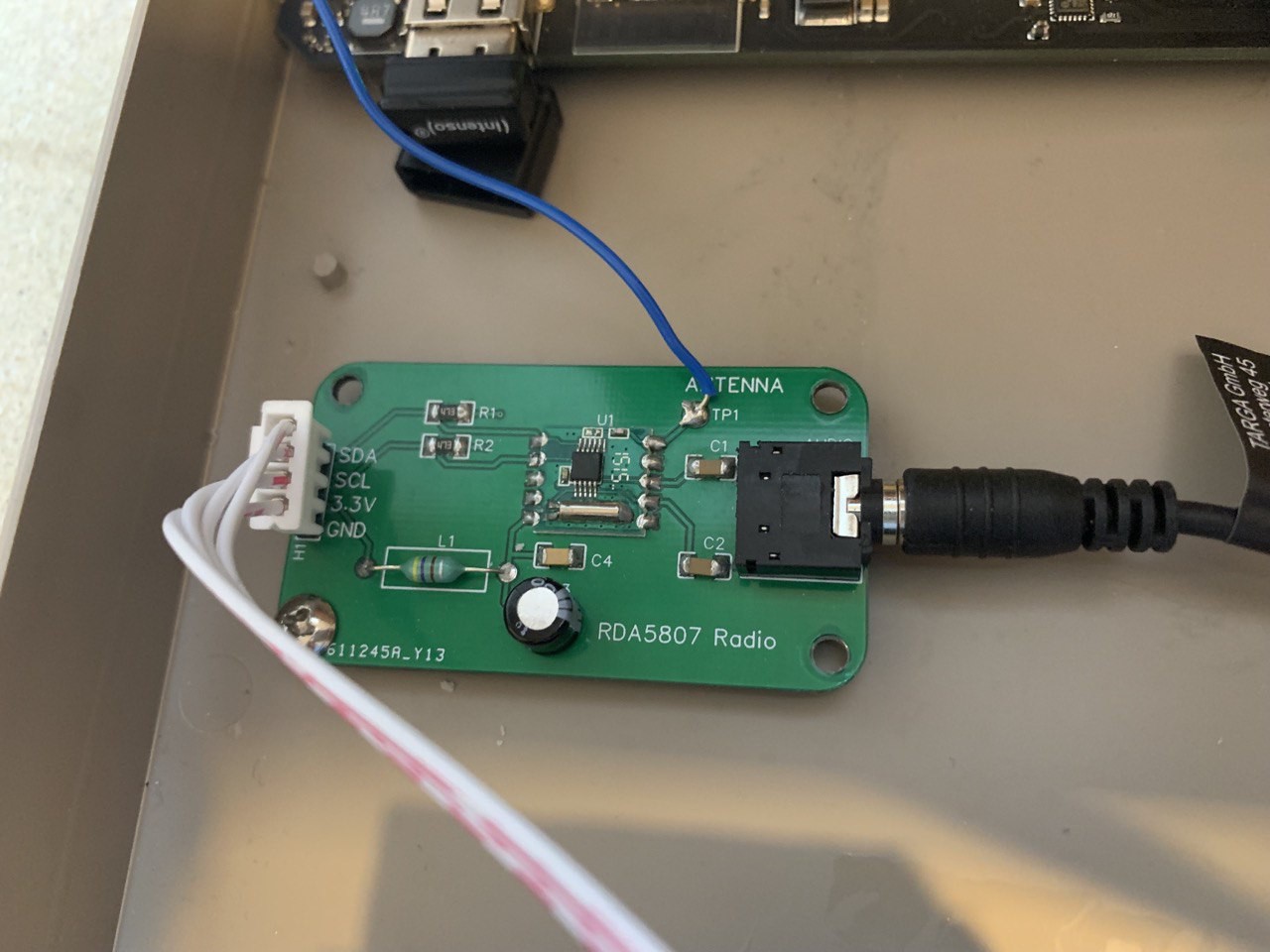
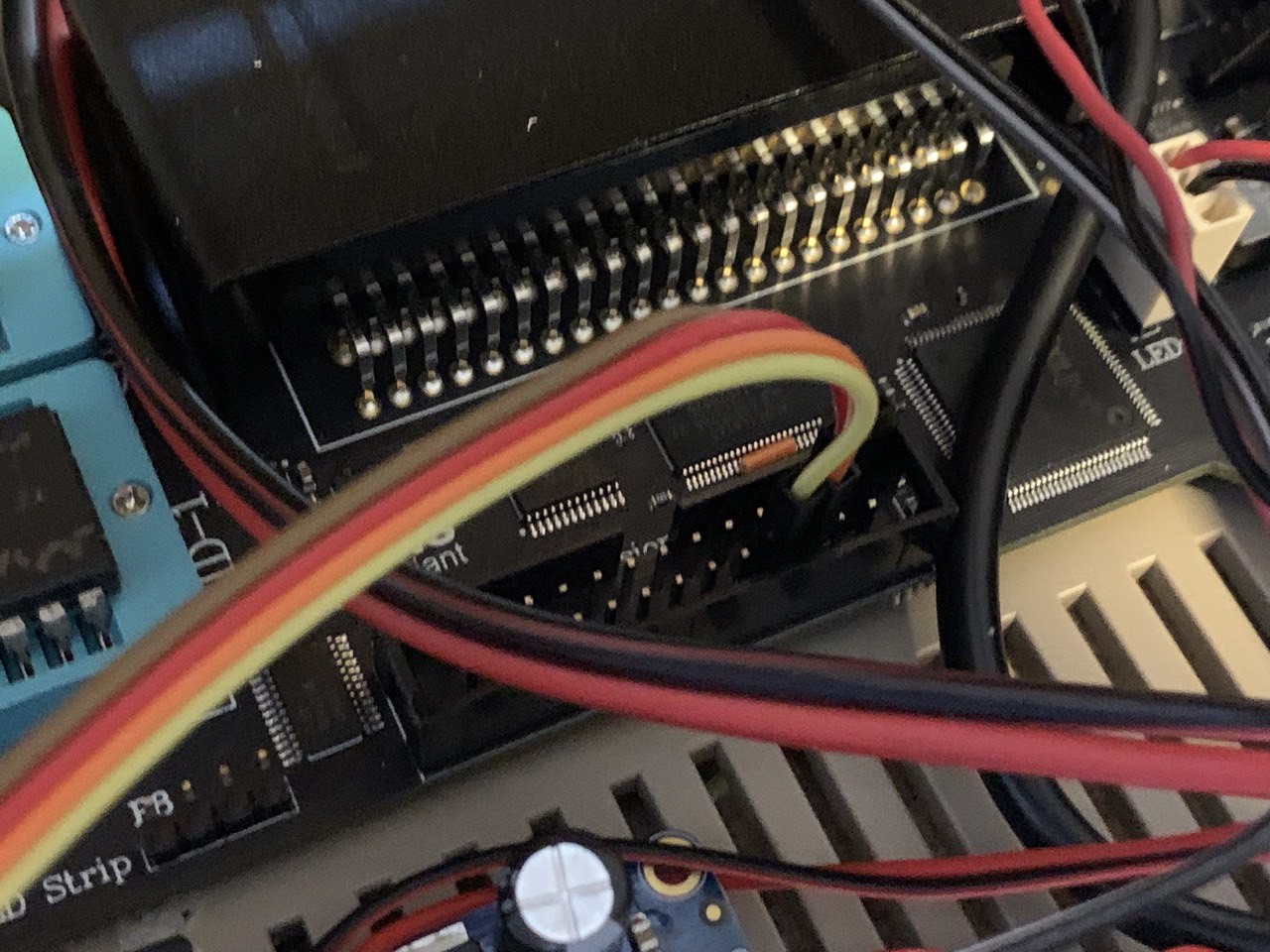
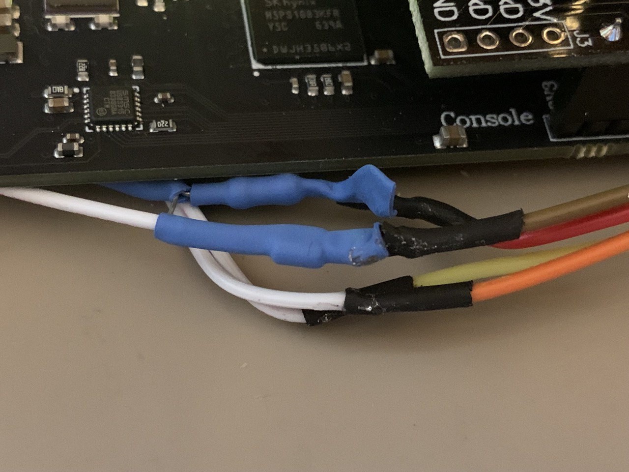
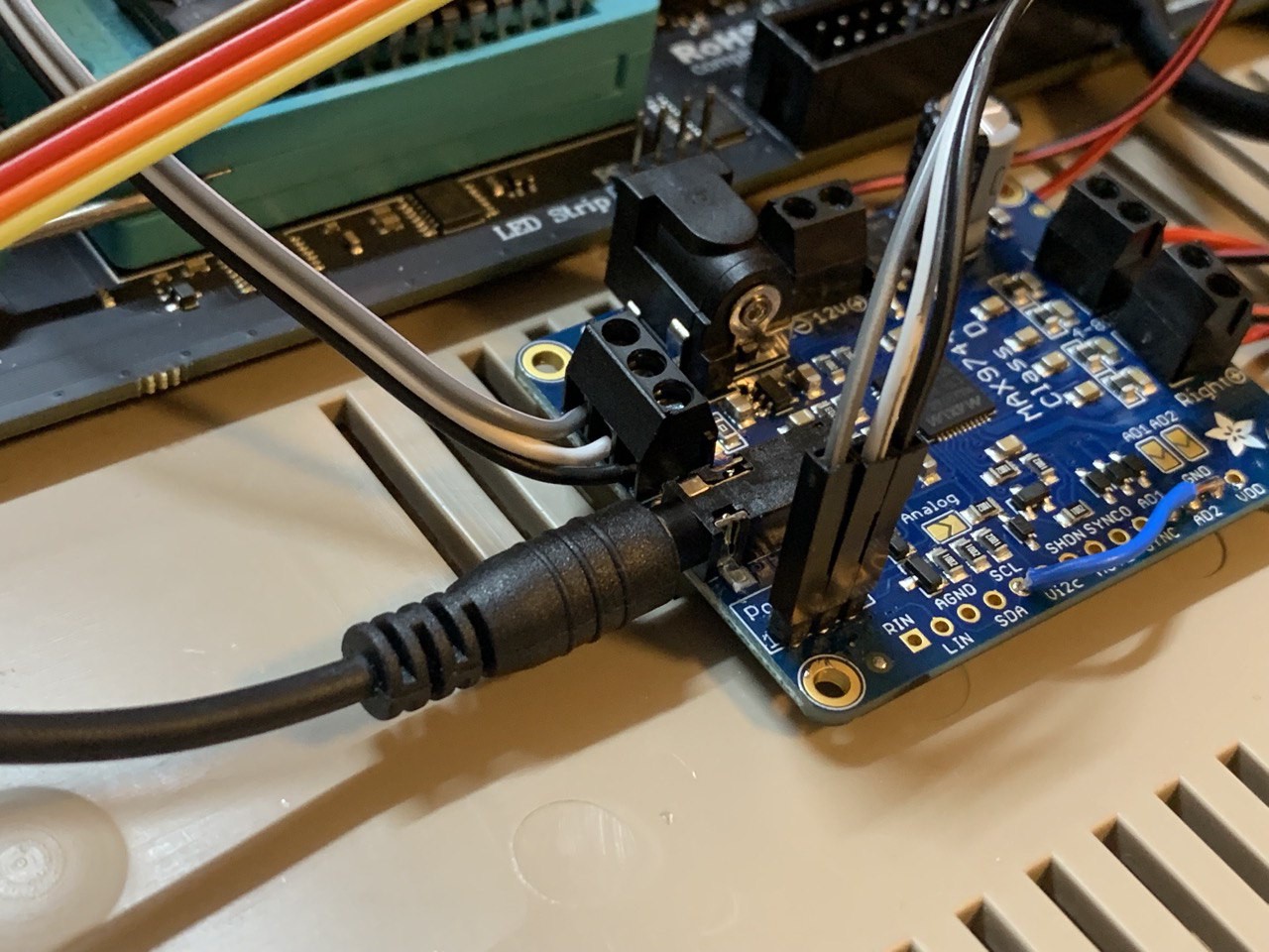
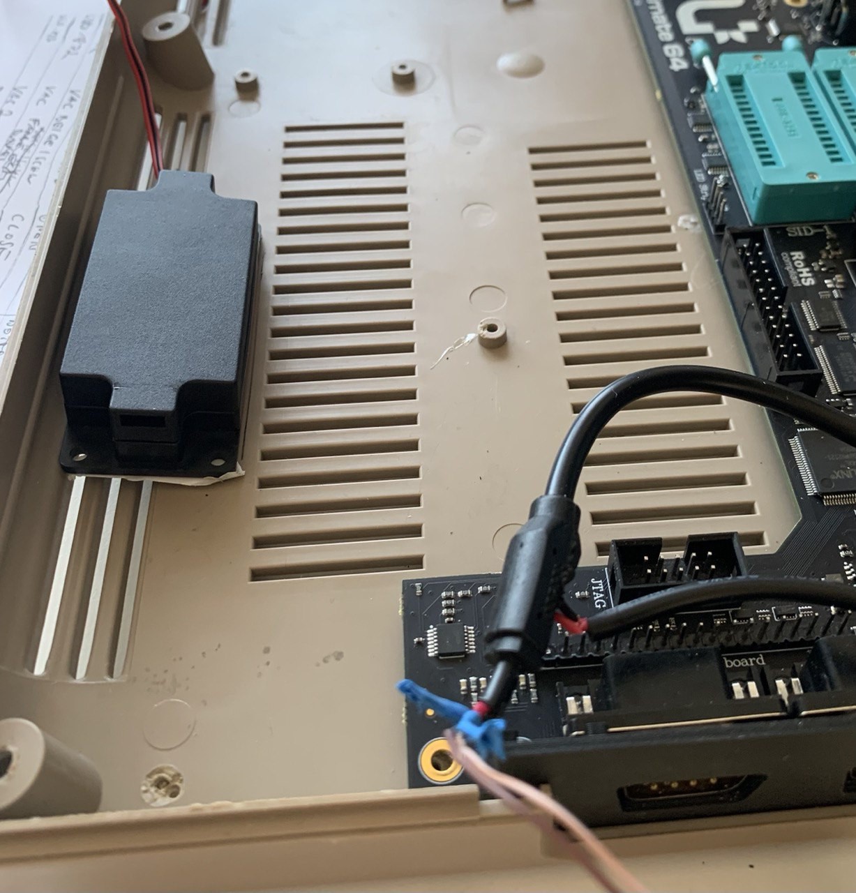
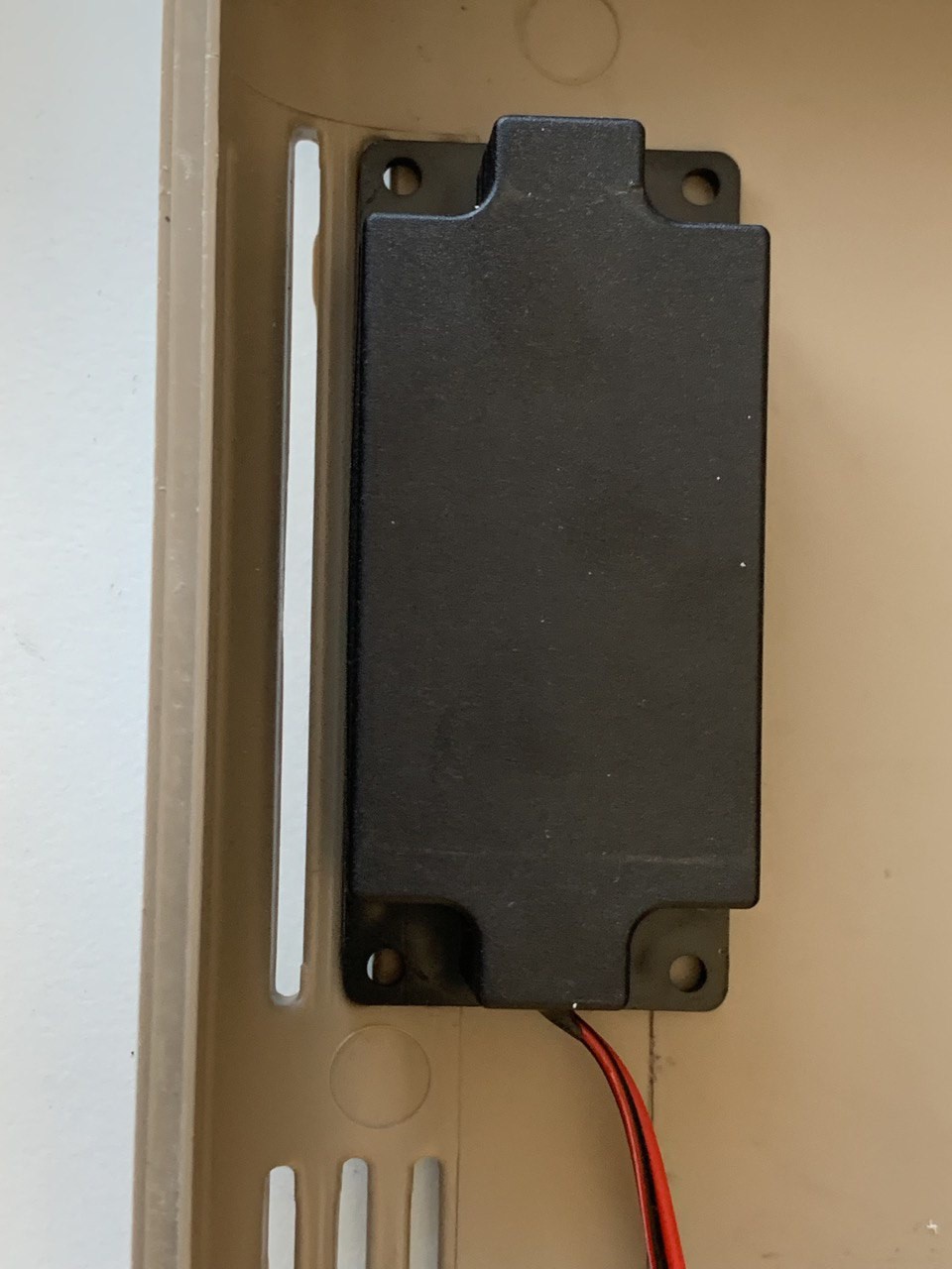
 Audio input is coming from the Sid Tap Headers, as described in my prevoius update. This means that the audio is not processed by any FPGA components on the mainboard and directly fed into the amplifier
 stupid
 Saul Cozens
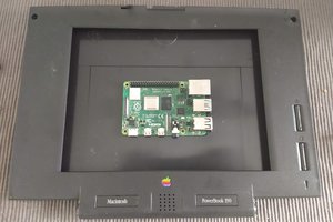
 Dan Jilek
 Lumor
Lumor