 Wernsey
Description
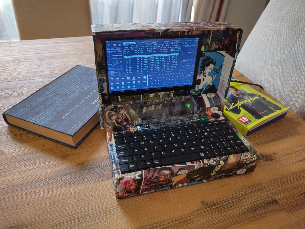
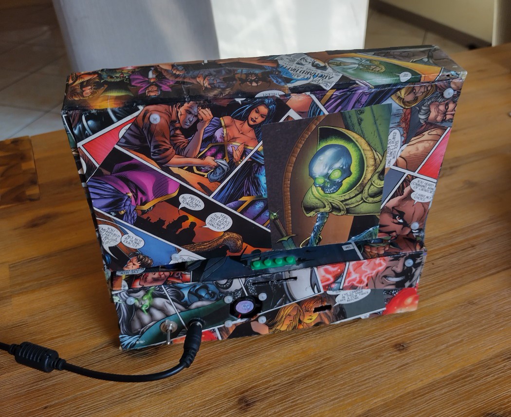
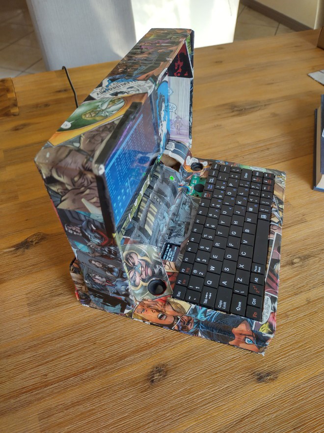
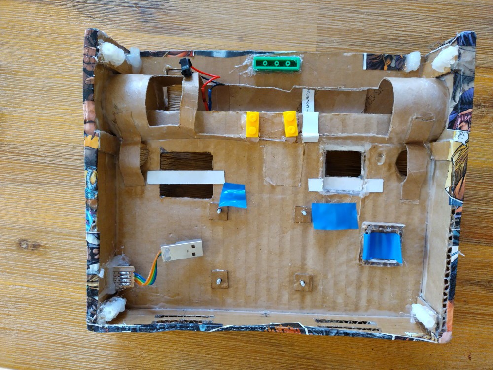
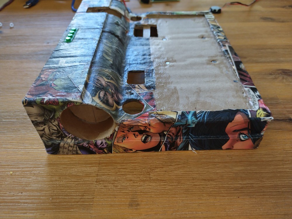
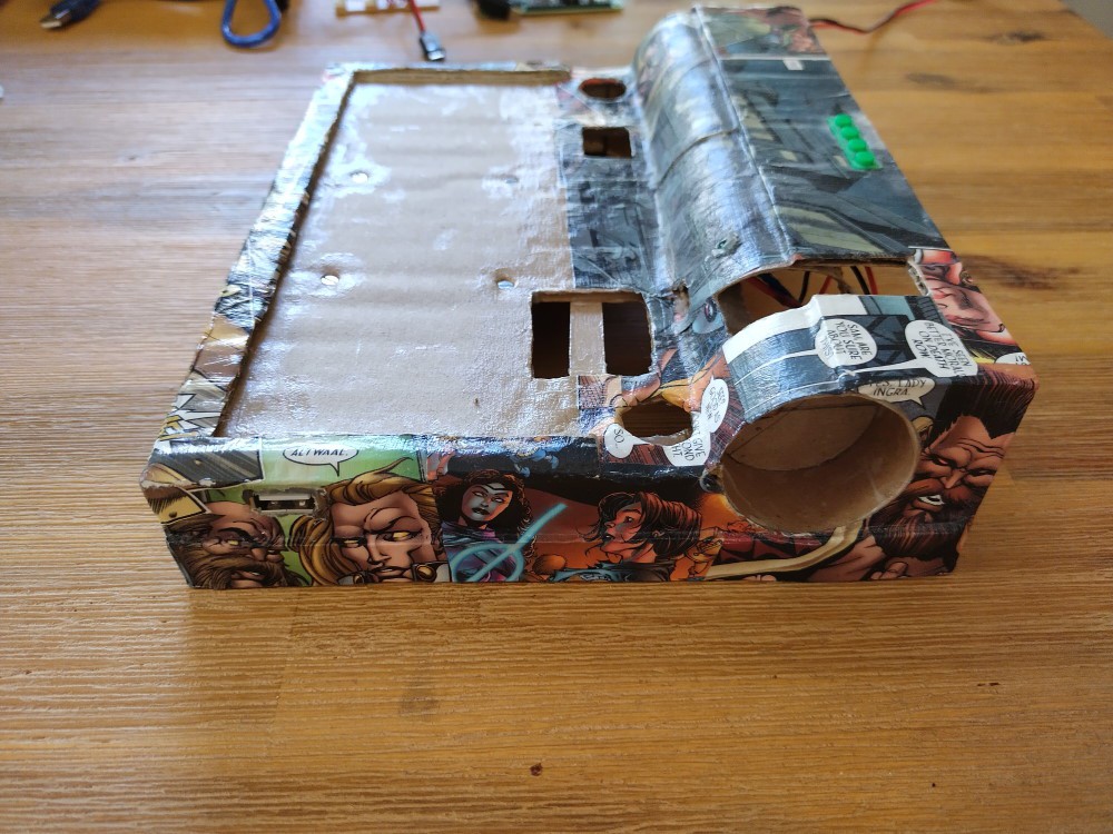
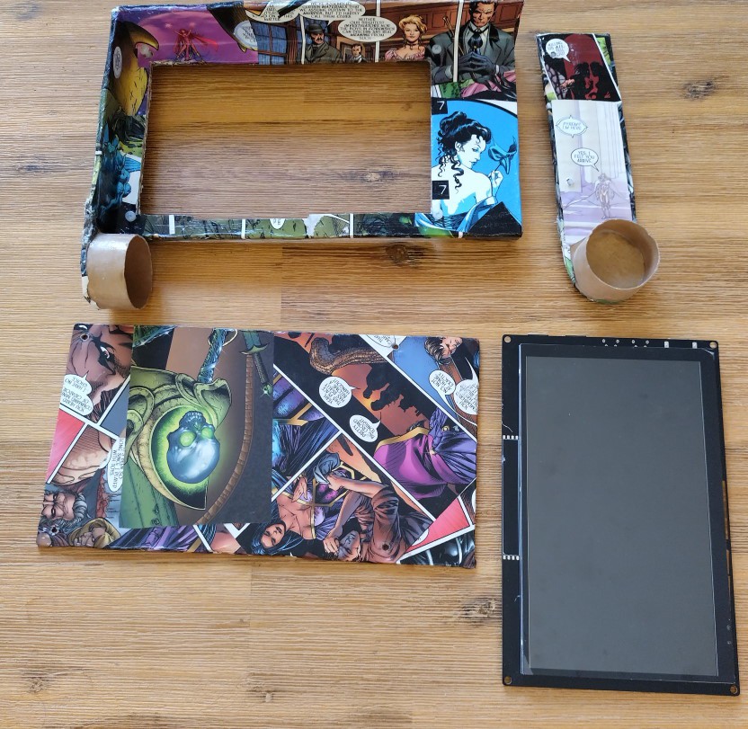
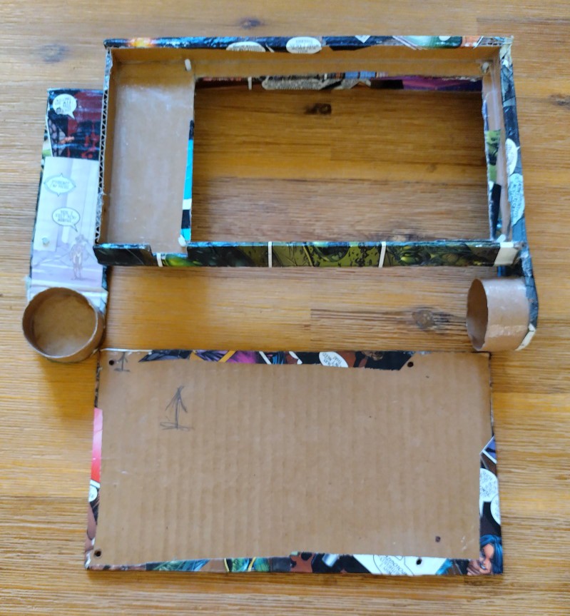
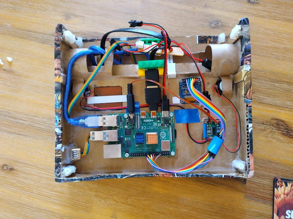
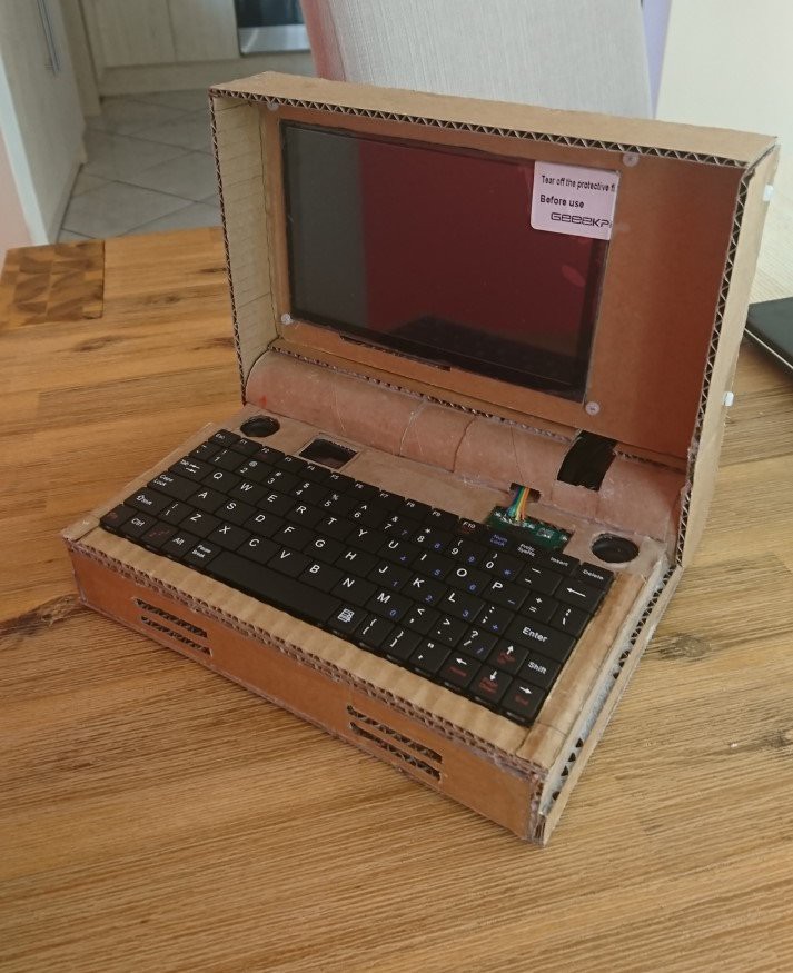
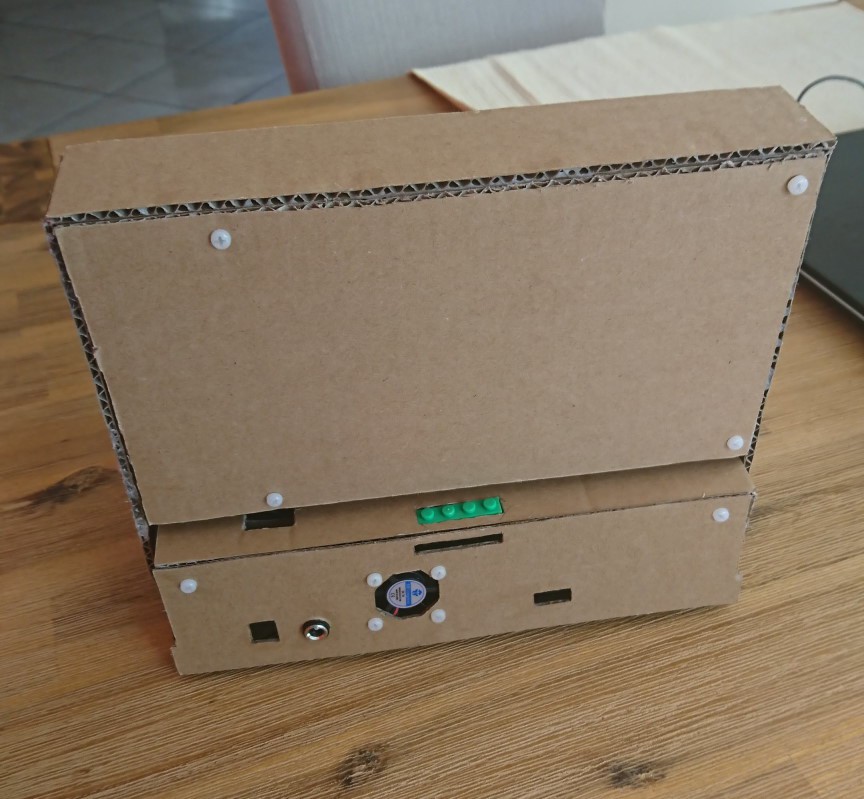
The Hack-in-the-Box is a Raspberry Pi 4-based Cyberdeck built from cardboard boxes.
It has
- a 7" touch screen display,
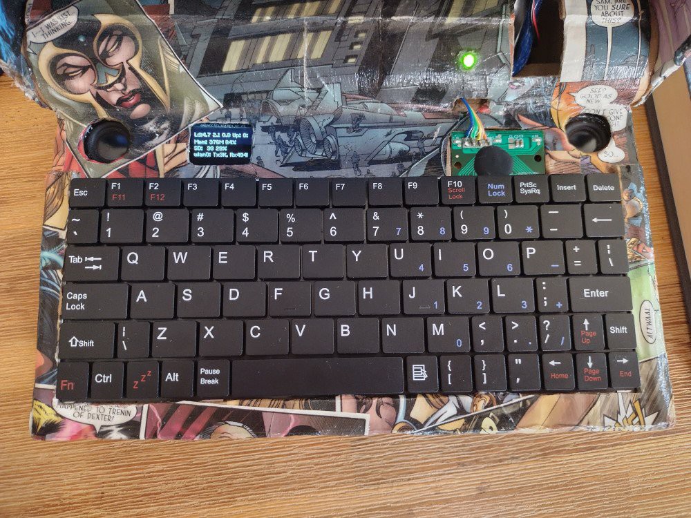
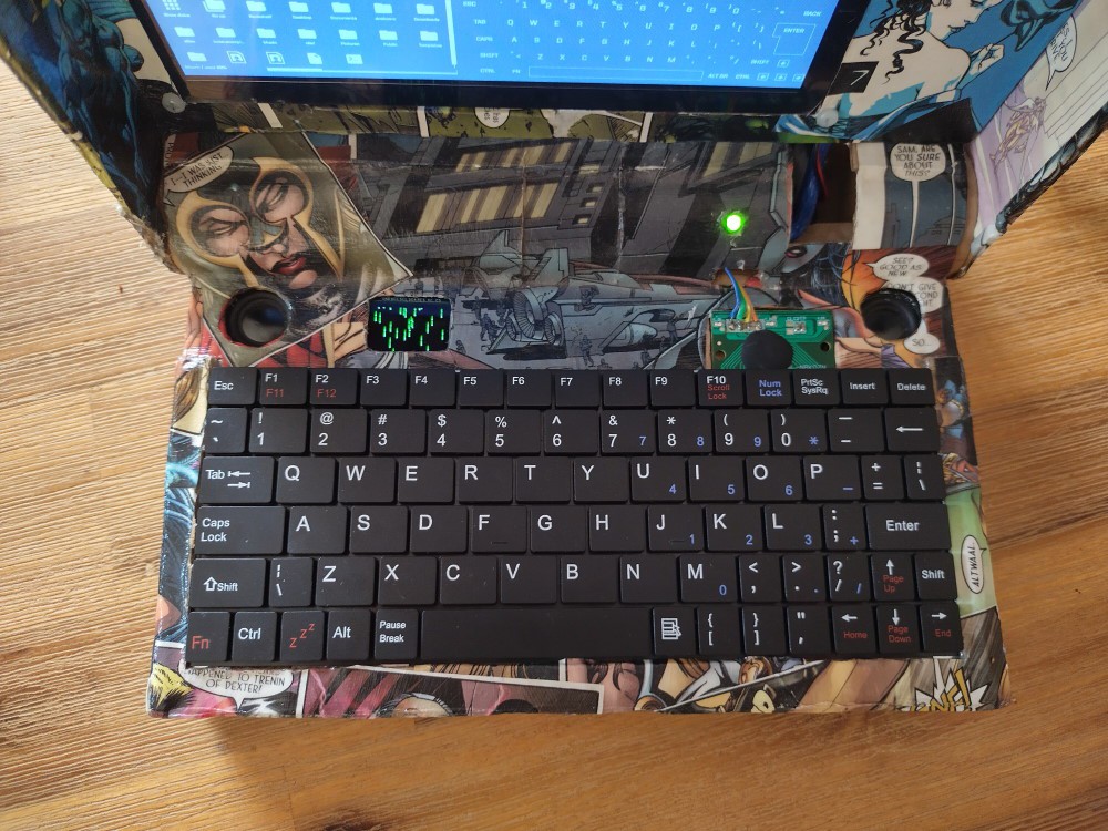
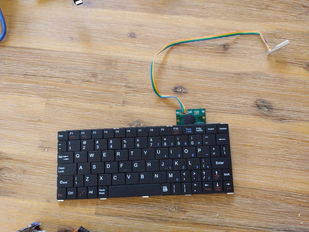
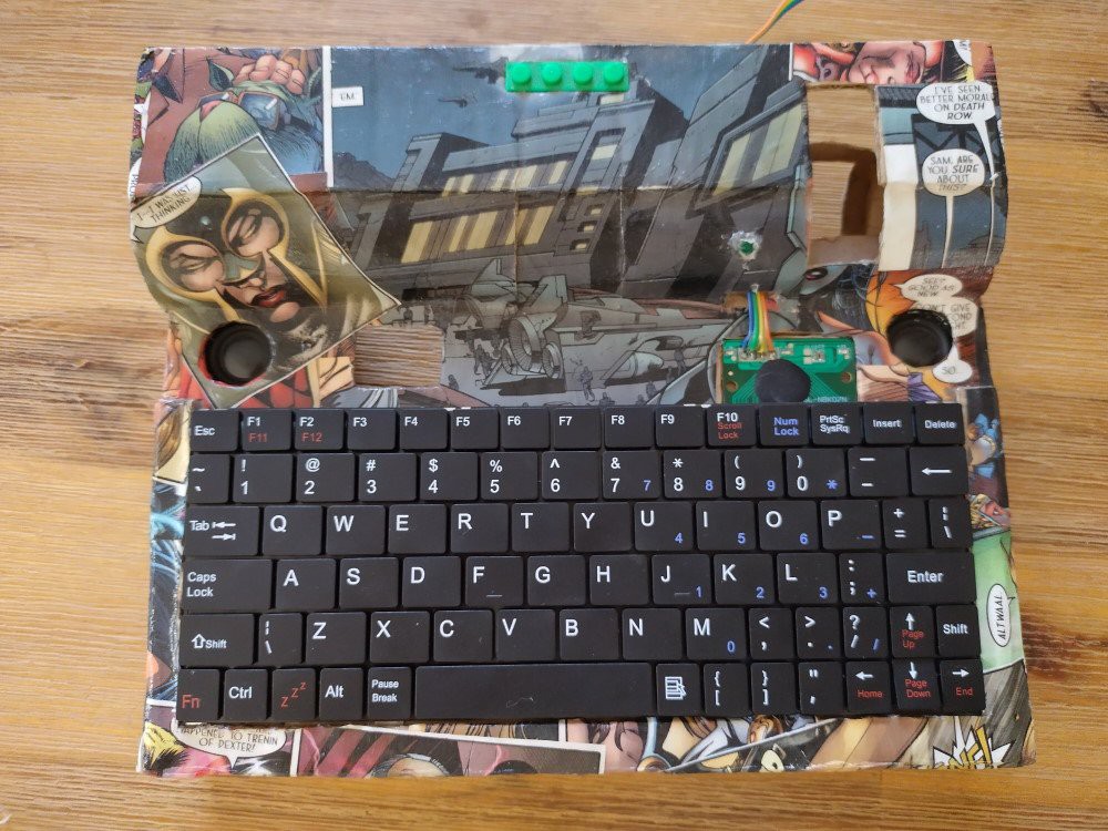
- a Qwerty keyboard scavenged off of a tablet cover
- a small 0.95" OLED display above the keyboard
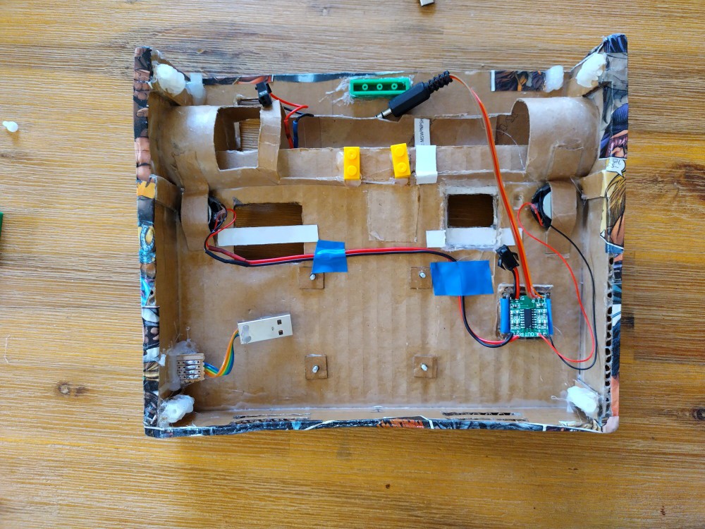
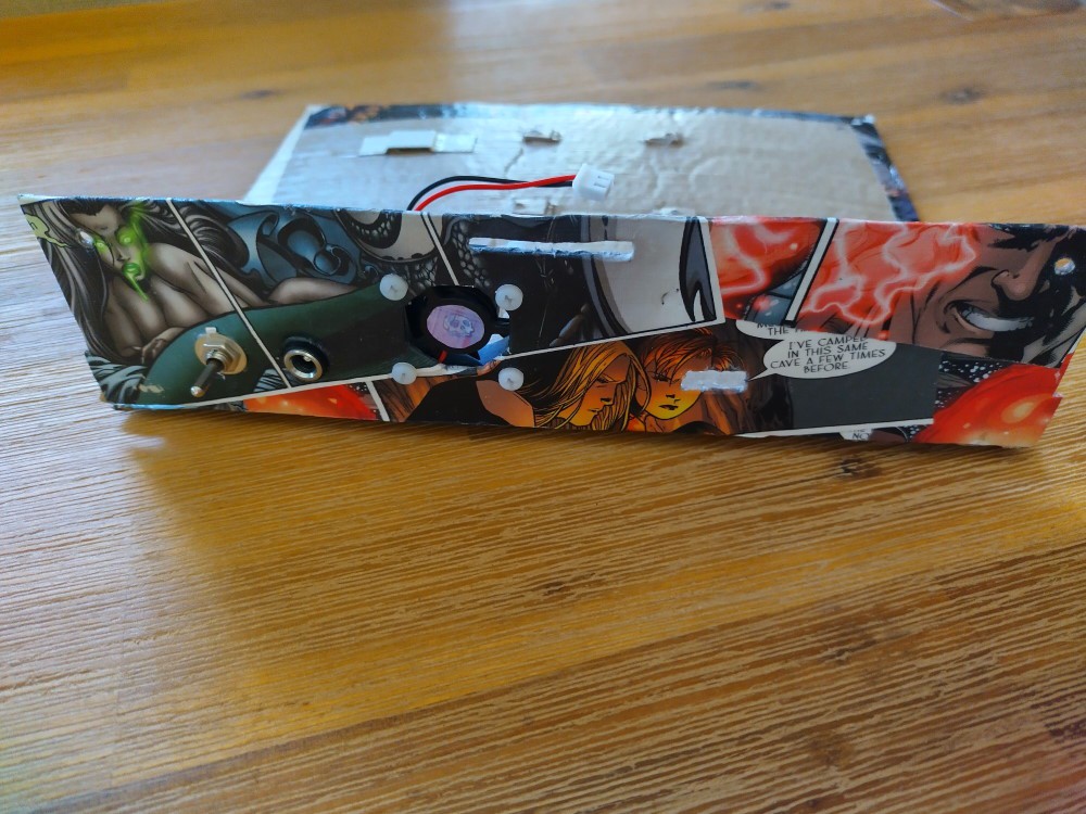
- an audio amplifier and 2 3W speakers
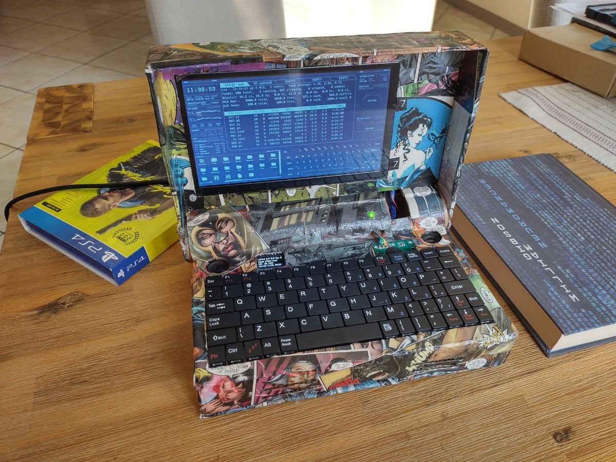
Here it is posed next to the two most cyberpunk things in my house: my copy of Neuromancer and the PS4 edition of Cyberpunk 2077 I pre-ordered in an impulse purchase:

Here it just runs Raspbian, with the eDEX-UI terminal emulator.
The OLED display is connected to the Raspberry's SPI interface that can be used to any additional information you might be interested in. I've been using the luma.oled library to drive it from Python, but the interface is fairly well documented.
Bill of Materials
- A Raspberry Pi 4
- Screen: GeeekPi 7" 1024x600 Capacitive Touch Screen.
- Here's where I bought it; here is a listing on Amazon.
- The keyboard is a "Volkano tablet cover 7" with USB Keyboard"
- I had a note of where I originally bought it, but the link is now occupied by a domain squatter.
- A web search for those terms yields the correct product, but I cannot vouch for any of those sites
- 0.95" color SPI OLED display
- This is the specific amplifier: PAM8403 Super Mini Digital Amplifier from Aliexpress - It is a very simple PCB based on a PAM8403 IC.
- These are the speakers I used: 4R 3W 23MM Round Speaker also from Aliexpress.
- Unfortunately they're also listed as unavailable
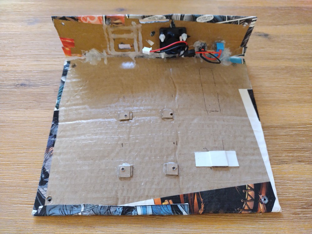
- This cooling fan DC 2Pin Mini 3010 Cooling Fan
- These heatsinks: 2 Pieces/Lot Aluminum Copper Cooling Cooler Heat Sink Heatsinks For Raspberry Pi
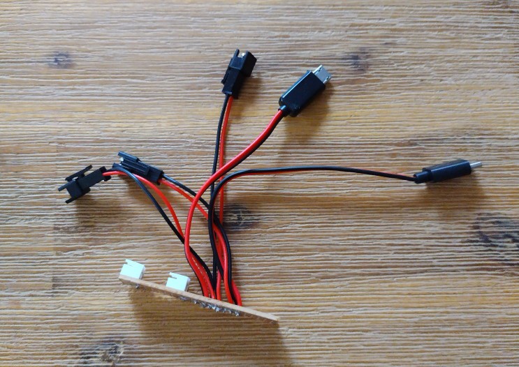
- A variety of USB connectors, mostly USB-A
- The keyboard has a USB-B connector, so it must be replaced with a USB-A connector to plug in to the Raspberry Pi.
- The box has a female USB-A connector on the side where a mouse or a memory stick can be plugged in. On the other side of that cable is a male USB-A connector that plugs into the Raspberry Pi
- The cable for the touch screen has a USB-B connector that goes into the screen and a USB-A connector that plugs into the Raspberry Pi
- The screen is supplied 5V through a USB-B connector.
- A male USB-C connector which will run from the power supply to the Raspberry
- A reasonably flexible but short HDMI cable to connect the screen to the Raspberry Pi
- A generic HDMI Female To Micro HDMI/TYPE D Male Plug Adapter
- Wires
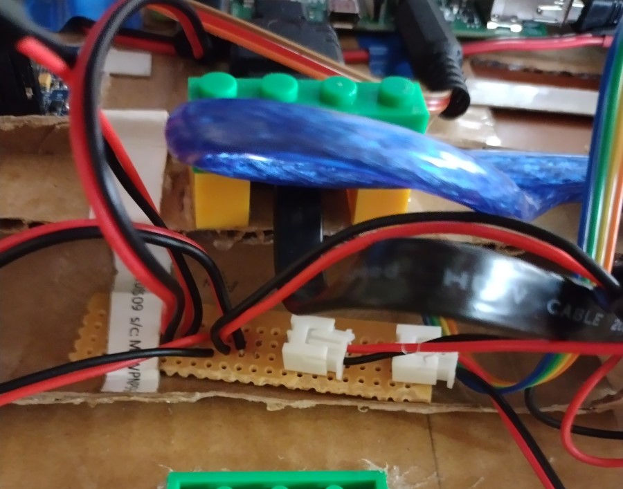
- Vero board
- Hot Glue
- An old comic book
- Mod Podge
- Nylon laptop screws and standoffs
- Some off-brand toy bricks


 MakeNModify
 Dylan Bleier
 Raphael
 knar
knar
Looks great!