Close
0%
0%

TimeFrame - The Desktop Time-Portal

amazing slow motion illusion for flowers and feathers

Similar projects worth following
Mind-blowing gadgets are rare these days. Very seldom will you stumble across something truly magical that leaves you in a state of confusion and amazement.

This project is inspired by water drop levitating installations such as shown by many museums around the world and the “Slow Dance” kickstarter campaign by Jeff Lieberman.

The illusion works using a combination of a strobe light to and a fast repeating motion. Each flash of the strobe light is illuminating a slightly different position of the object that is actually moving too fast to see with the naked eye. Due to the small difference between the frequency of the motion and the strobe light, a slow motion effect is generated that suggests the object is only traveling very small distances from strobe to strobe. The frequency of the strobes is between 75 and 85 Hz and is not visible.

TimeFrame_3_0_simple_instructables_1KB.ino

uses 716 bytes + 9 bytes dynamic

ino - 1.44 kB - 12/03/2016 at 10:10

Download

  • 1
    Step 1

    You can get the kit including all parts here: http://www.cubic-print.com/TimeFrame

    Tools

    • Soldering stuff
    • Battery-powered screw gun
    • Various drill bits(2mm, 3mm, 6mm)
    • Pliers & wire cutter
    • Mini USB-B cable for programming the Arduino

    Frame

    • 1x 12V 1A power supply
    • 1x picture frame (at least 25mm deep, better 35mm)
    • 2m LED stripes (3 pieces of 60cm each)
    • 1x thin metal plate like thickness metal gauge (thickness: 0.3mm size: 10x70mm)
    • 1x rod fixation plate (eg. Aluminum 20x55x2mm)
    • 1x wood block about 4 mm longer than the iron core
    • 3x wood screws + washers
    • 1x iron rod / screw / nail (length around 60mm diameter: 6-12mm)
    • 1x fixation for iron rod like M6 bolt or just a nut in case you use iron screw
    • 45m (=40gr) 0.41mm (AWG26) isolated cooper wire
    • 3x small Neodym magnet (d=10 h=2)

    Electronics

    • 1x Atmega Nano V3.0 328P
    • 1x Capacitor 16V 4200 uF
    • 2x Mosfet IRF44N
    • 2x 10K Resistor
    • 2x 300 Ohm Resistor
    • 2x Diodes 1N4007
    • some cables for LED connection
  • 2
    Step 2

  • 3
    Step 3


    Cut 3 LED stripes with a length of 600 mm each. Only cut the stripe in the position indicated with a scissors symbol on the stripe.
    Connect all 3 rows in parallel. Pay attention the printed polarity on the stripe. Depending on where you cut the stripe “plus” and “minus” might not be on the same side for all 3 rows.

    Glue the LED to the inside of the frame. Connectors are on the right side. To achieve a good performance even in normal daylight cover the left, right and upper inner side of the frame with 3 rows of LED stripes. For 600mm stripes start 5cm above the bottom to get it symmetrical. The 3M tape of the stripes might not be sticky enough for paper frames. Just use additional glue to fix them.

View all 5 instructions

Enjoy this project?

Share

Discussions

ElBawkBawk wrote 03/05/2017 at 02:15 point

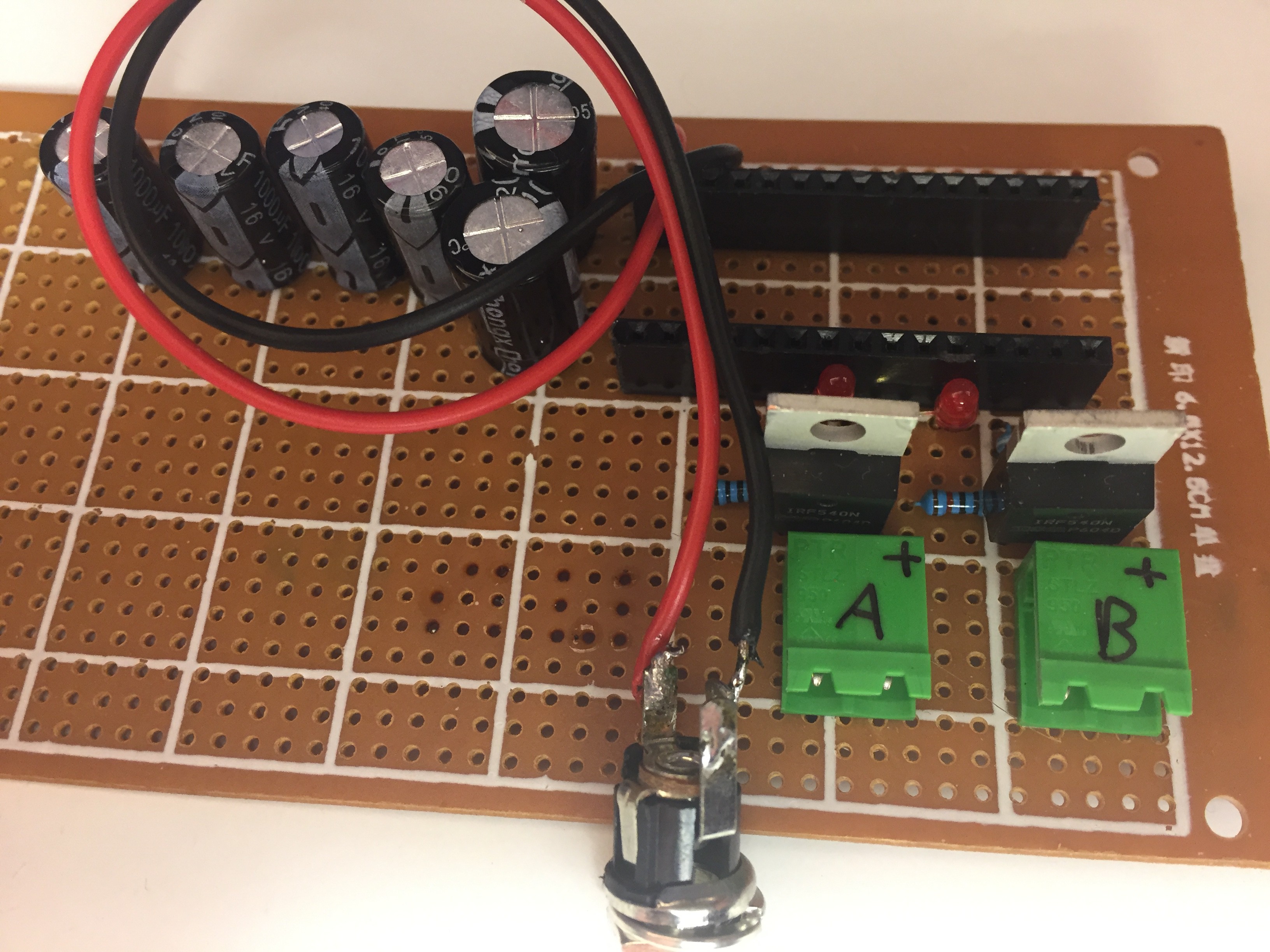
This project finally inspired me to buy a soldering iron and make a gift for our anniversary.  One thing I notice is dimming of the lights, to a point where it becomes too flicker-ish.  I notice the higher the magnet's power, the worse the timing is on the leds.  Given this is my first noob project, could anyone point me in the right direction to troubleshoot this?  My background is in software/server administration, so schematics are a whole new set of logic rules for me.  I'm guessing the capacitor is to help alleviate this, so my guess is perhaps too much copper in my coil, or just my shady soldering skills.  Any help or direction would be appreciated.  Thanks guys!  And thanks for open sourcing such a great project.

  Are you sure? yes | no

Similar Projects

Does this project spark your interest?

Become a member to follow this project and never miss any updates