Close
0%
0%

Jack of all Trades Cyberdeck

When a Jack of all Trades Jacks In.

Similar projects worth following
A Makers Cyberdeck!

Features: Modular Setup, Touchscreen, 2nd screen for sys info, storage, hidden lockpicks & cuff key, oled "company" screen display, electronic repair package, L bracket support for attachments, removable portable battery, powered usb hub, and more!

Starting off, this is my first cyberdeck. I have always wanted to make one and when I realized the legend Gibson himself would lay his eyes on my creation, I knew it was time to make one.

The goals for this deck: 

1. MODULAR!! I wanted this to be a portable workstation that could be modified for whatever project I was working on. 

2. No 3D printed parts!! Just to show all of you, without access to a 3D printer. You can still make a unique and great looking deck. ( I personally have an ender 3, but thought this would be fun )

3. Made from as much recycled parts and materials as possible!! I imagined what it would be like in the sprawl, and wanting to build a deck. What better way than using whatever you can find and have access to? It's better to spend money on the important things like hardware! I've always been a function over form guy.  ( In the end, the only things purchased for this was the keyboard, touchscreen display, and having custom sticker I designed made for flavor)

In its current state for the Cyberdeck Contest. It has the following features:


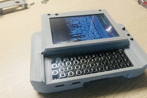
Raspberry Pi4. Main display is touchscreen. 2nd display for sys info (using AIDA64). Completely modular, I achieved this by utilizing mobo standoffs and Velcro. 2.4 and 5G wifi usb adapters,   Removable 20000 MaH battery for "on the go" use. Also can be powered via an outlet. OLED display ( on startup produces "HIGH TECH LOW LIFE, then after 10 seconds it switches to "MODICUM TECH" It is run by a rp2040 feather, that is easily accessed for additional use). Wireless keyboard with elven/english letters (because I love shadowrun!). Aluminum body with storage, one section has a foam cutout inserted with lockpicks and a handcuff key that is easily removed for access, the other holds a pico, ceramic capacitors, mobo standoffs, (2) .92x128 OLEDS, 400mah lithium batter. A usb hub that can be powered on its own, so you can use external hard drives or other things that just the pi cant run with its own power. Modular parts include, an Arduino uno, mounted ssd, mounted prototype board to solder, a small "box" that holds a plastic bag with capacitors, resistors, diodes, pico, and another prototype solder breadboard. Removable plastic cover's to access the storage. An aluminum piece on the side, that an L bracket can fit into. I used that to produce the ability to add a breadboard, or voltage tester. Also a side attachment to hold whatever your soldering with. One of the L brackets used has a strip of velcro attached to it, so adding additional modular items in the future will be easy! It also has some custom stickers I designed in photoshop, to give it some flavor. Then obviously it's loaded with a ton of software for circuit designing, coding, communication, pentesting etc!!!

 ( Since deadline is right around the corner, I'm going to write out my process. Then give a link to a gallery of the abundance of pictures I took of the process. I don't have time to format all the pictures sadly. And make an extremely detailed write-up. In the future I will edit them so this post will have pictures. And make things more cohesively written. But making the deadline for the contest comes first!! )

Additional pictures can be found on my photobucket, and in the file section.

https://app.photobucket.com/u/nicktalife/a/b583971d-15de-4f3e-9d6c-155cd314fb2d

JPEG Image - 1.87 MB - 09/29/2022 at 01:59

Preview
Download

JPEG Image - 2.42 MB - 09/29/2022 at 01:59

Preview
Download

JPEG Image - 2.39 MB - 09/29/2022 at 01:59

Preview
Download

JPEG Image - 2.10 MB - 09/29/2022 at 01:59

Preview
Download

JPEG Image - 1.64 MB - 09/29/2022 at 01:59

Preview
Download

View all 91 files

  • 1 × keyboard wireless
  • 2 × display touchscreen/regular
  • 1 × aluminum
  • 1 × plastic
  • 1 × rp2040

View all 6 components

  • 1
    ALL IN ONE GO!!

    I loved playing shadowrun as a kid. So wanted to add a 6th world flavor. Elven text was perfect for that! So I purchased a wireless mechanical keyboard, that had english and elven text.

    Next, I took some aluminum that I had from another project and cut it to the same size of the width of the keyboard. I made two pieces. The aluminum is rectangular and hollow.

    After that, I used some JB Weld to attach one to the keyboard. Then affixed the other piece, to the first one.

    I also had some other leftover aluminum, it was a flat piece that was the same width of the two rectangular pieces. So I cut it to size, and again used the JB Weld to attach that on top.

    Once it was all dried, I cut a rectangular hole in the top left of the aluminum to be able to use an OLED display. The display is run by a rp2040 feather. I didn't want to power that on it's own, adding more wires. So I hardwired it to the Pi4 itself! I used heavy duty double sided tape to secure the display inside the aluminum. I then cut some lexan, to put over the display to protect it and make it flush. There were leftover cut marks. So I took an old cover to a candle, and cut that to cover all my mistakes. I sanded it down so it wasn't black anymore, and looked the same as the aluminum.

    I had to attach the screens obviously. So I made some additional pieces just for that. I used old HD holder's from salvaged computers. I cut some aluminum to size, used JB weld to attach it to the metal HD holders, Then cut the HD holder's, so it was an L shape. I drilled holes in them to be able to mount the screens using mobo standoff's, and also making it modular.

    I took the main screen I purchased, and put it together with the Pi4. But how was I going to attach the screens to the alluminum? I wanted them to be adjustable. So, I dug through a box of old/unused hardware. I found some hinges that were perfect for the job. I attached the hinges to the 2nd screen using heavy duty double sided tape, on the back of it (a plastic piece that came from a raspberry pi kit) Then mounted the hinges/screens to the aluminum using mobo standoff's and nuts. However, to attach a hinge to the main screen, I had to cut aluminum in a wide "U" shape, and attach that via the mobo standoff's on the screen. The hinge was then attached via small nuts and bolts.

    I wanted to be able to use the inside of the aluminum for storage, and also wanted to be able to access the rp2040 attached to the oled display easily. So I cut some more rectangular holes in the back, and bottom of the aluminum. I then cut a piece of aluminum to affix to one end of the aluminum. The other end I made a removable plastic piece out of an old plastic license plate cover! I also used the same plastic to make covers for all the other holes I cut in the aluminum.

    To be able to fit the big battery bank I had on the underside of the aluminum, I needed some clearance. So I drilled some holes in the aluminum to be able to use mobo standoffs to lift it a bit. The battery bank is attached to the aluminum via double sided velcro tape. Making it removable, and also making it so that I can change the height of the cyberdeck depending on circumstances.

    Now that the main screen was attached, and put together with the Pi 4. I affixed a usb hub I wasnt using to the back of the plastic covering the Pi using strong double sided tape. This USB hub also has the ability to be powered on its own via a charger and outlet. That way I don't have to worry about undervolting the Pi while using things that draw too much power, such as external HD's.

    Since the underside of the aluminum was roughly only 40% utilized. I thought of what else I could affix to the bottom, via the double sided velcro. So I made a small "box" using a salvaged plastic SSD holder from an old pc, more of the plastic from a license plate cover, mobo standoffs, and some small ziptie's. This is used to hold various electronic components, Pico, and a solder ready breadboard. 

    I couldnt fit breadboard wires in the "box" I made. So I found a plastic tube that was the perfect size to hold a small handful of wires. I once again used double sided velcro to affix it to the underside of the spot the 2nd screen/modular space is. 

    While going through all my various "junk" salvaged from old computers, other electronics, and leftover parts from other projects. I found a unique looking piece of aluminum. It was perfect for using those simple L brackets that come in various shapes and sizes. I affixed that with JB Weld to the side of the aluminum for MORE MODULAR AWESOMENESS!!!

    As for utilizing that oddly shaped piece of aluminum, I took a small L bracket, and put some double sided velcro on it. I took a small breadboard, and did the same. Now I can work on electronics with the deck!! 

    I also made another piece that can hold your soldering device safely. I acheived this using more salvaged plastic, some cut pieces off a steel sheet, a brass eye hook, some screws, and another L bracket! 

    As for the other modular pieces in the profile picture you see, such as the arduino, the prototype breadboard, and ssd. All those pieces were simply made out of the plastic from the license plate cover, and some mobo standoff's!!!

    To clean it up, and pull it together. I sanded excess JB Weld away, painted certain parts black, and added some flavor with the sticker I designed! 

    Like I said, I know this is not fully detailed. Lacking pictures as well. However, I will do a future edit making this a bit more comprehensive, even detailing the small features. I hope you enjoy my maker's cyberdeck build, because I sure as hell do! I will definitely be adding additional modular features, and will update this project more in the future!!! 

View all instructions

Enjoy this project?

Share

Discussions

Similar Projects

Does this project spark your interest?

Become a member to follow this project and never miss any updates