 Sagar 001
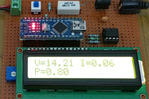
Power monitoring is the basic need of any electronics or electric system nowadays, if you are a hobbies or working on any hardware related project. Now I have a portable wattmeter available which has functions to measure the DC voltage, Current and overall power.
Basically, it is a watt meter which is also comes in the lab bench power supplies. But we are just measuring not making any constant current/ voltage supply in this tutorial. That is the content to be done in another video/ article. This project is bought to you by JLCPCB- China based PCB manufacturer, has a 15 years’ experience in this industry.
Problem in measuring:
Arduino has two type of measuring capability voltage and time duration. Arduino can measure voltage using the 10bit ADC which can provide a great resolution up to 20volts. Somehow If the current can be converted into voltage form, it can be easily measurable. But to do this either we have to go old shunt-based voltage drop configuration or we can go with readymade hall effect current sensors. ACS712 comes with a precision current measurement of 100mv/A.
ACS712 and its types:
ACS712 comes in different current selection chip. It has 3 variants one for 5Amperes, second for 20Amps and next for 30Amperes. ACS712 comes with linear graph of respective voltage when there is increase in current. Here I am using 20 ampere version but 5ampere is recommended for better precision in small electronics readings. Code can be modified as per used variant.
Components required:
1) Arduino Nano
2) ACS712-20A
3) 4.7K and 10k resistor
4) OLED display
5) External SMPS power supply
6) Usb and connection wires
7) Custom PCB shield from JLCPCB
Circuit diagram:
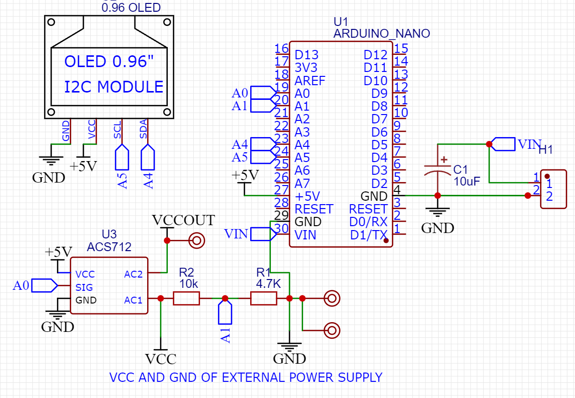
Arduino ADC has a maximum range of 5volts, so if you want to measure voltage more than 5volts then a voltage divider network is required. Here I made a resistor network using 4.7k and 10k which gives the final range of 16.6volts. Just do a little bit calculations over the voltage divider network.
OLED is connected using I2C bus to the Arduino, ACS 712 also needs a constant voltage of 5volts. It is to be noted that the readings of voltage and current is based on the 5volt regulation, resistor tolerance and room temperature. The practical readings are always different from theory. When we have both current and voltage, power can be defined using the formula: voltage x current.
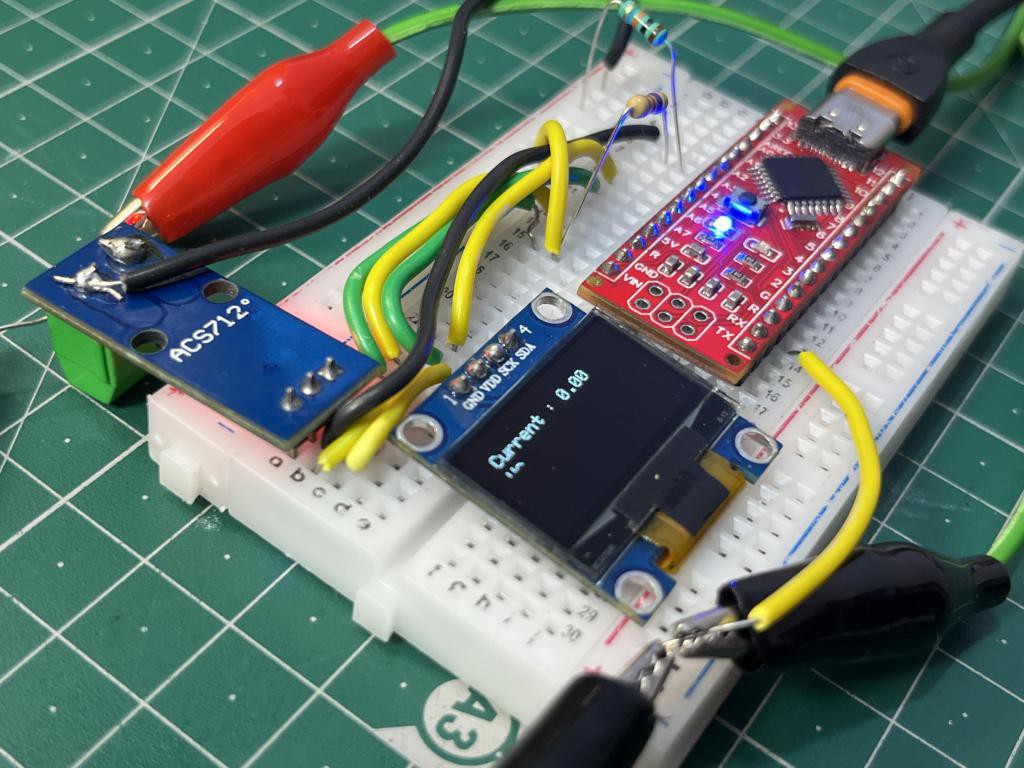
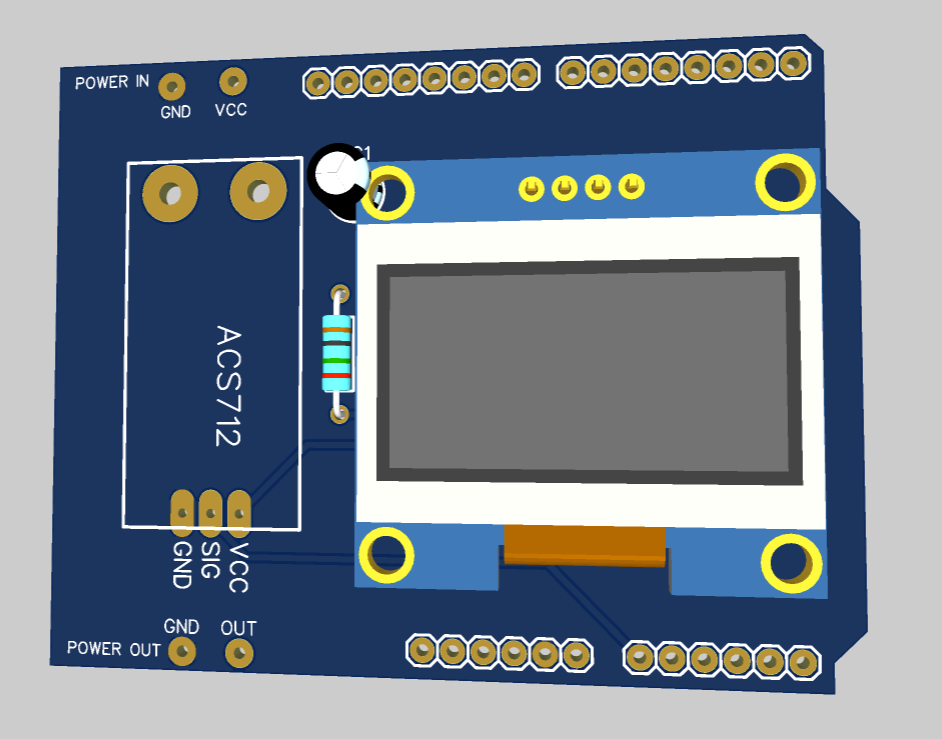
PCB shield:
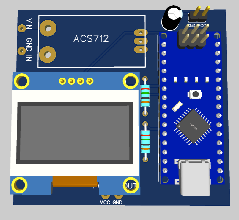
Just plug your Arduino, OLED and ACS712 sensor. Solder some resistor and capacitors and we are ready to go with this wattmeter project. Values can be calibrated through the program. I made this shield in EasyEDA and then fabricated by JLCPCB in China’s best lab.
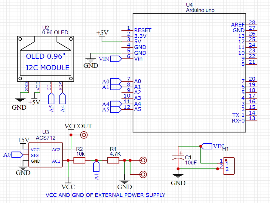
Or you can go with Arduino UNO based shield which provide a better interface, just plug you shield to Arduino and go for it. You can download all the required file from below.
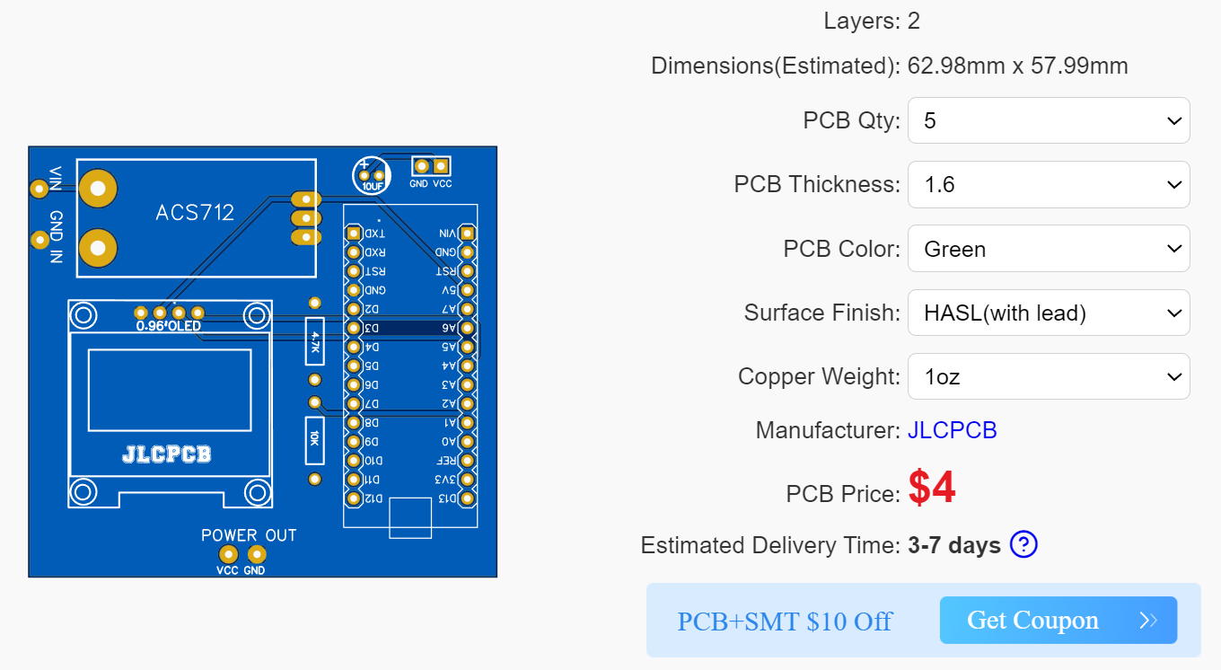
Get your hands on the best manufacturer service form JLCPCB just in $2 for 5pcs of 2-layer boards. Sign-up now to JLCPCB and get free new user coupons of worth $54. Download the code, Gerber and schematics from here or you can also try your own design with modification by taking a reference from this.
Code:
All the basic libraries are used in this program and you can get them from manage library section under tools menu in Arduino IDE.
// Suitable with 12v battery, adaptor wattage, current and voltage monitoring.
// Resistor divider network need more upgradation if voltage is higher that 15.6
// Try 0x3D OLED address if screen did not work.
// Precision of the voltage depends on the tolerance of the resistors.

#include <Wire.h>
#include <Adafruit_GFX.h>
#include <Adafruit_SSD1306.h>

#define OLED_RESET -1
Adafruit_SSD1306 display(128, 64, &Wire, OLED_RESET);

void setup() {
  // put your setup code here, to run once:
  Serial.begin(9600);
  display.begin(SSD1306_SWITCHCAPVCC, 0x3C); // Change the address to your's one
  display.clearDisplay();
}

void loop() {
  // put your main code here, to run repeatedly:
  int adc = analogRead(A0);
...
Read more »

 hIOTron
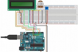
 Lithium ION
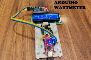
well done, will build it.. but, U are using "i like studio" - but i dont! U cant see the video, too small