 Jean Alinei
Hardware is Hard !
We wanted to give a quick summary of our different preliminary prototypes and their weak points so that it might be useful to someone !
When you design a project you always want it to be simple to debug and to be quite robust so that it meets the initial objective. Our thoughts were rather to make a product that can be assembled and maintained easily rather than to make it super robust and integrated from scratch. As such, we wanted to test out the design function by function, and assembling them as lego blocks.
We also wanted to comply with as many "standards" as possible - usually mechanical parts tend to account as big expenses in the final BOM - Especially when you have designed your board with funny dimensions, and you need a non standard heatsink or casing. So we naturally decided to limit ourself to the 100mmx100mm that became quite popular because of PCB manufacturers special offers - while still possibly comply with the 19" racking system standard sizes. (3U format is 100mm tall). We tolerated to increase the PCB surface up to 160mmx100mm to match with the EuroCard format.
#1 An attempt at using PCI standard to get cheap connectors
This is a really old attempt but it is still worth documenting as it turned out pretty well - We used a 36 contacts PCI connector to tie a micro controller board to the power stage. This was really cheap, as we only had to pay for one standard connector to get 36 contacts.
The big downside is that it is not low profile at all, and the size of the micro controller board will give the final height of the product which can ends up adding a lot of cost to the casing.
Second downside here is that you need to concentrate all the signals to the same spot on the design so you quickly end up mixing analog signals and digital signals at the same location which is not good practice.
#2 An attempt at building a vertically integrated prototype with headers
This prototype had no name, and was built with 4 different pcbs stacked on each other with headers.
- The power PCB with the switches, power inductors and capacitors and current measurements
- The driver stage with the mosfet drivers
- The measurement stage with the voltage measurements and the feeding system.
- The micro-controller board that was a nucleo board back then.


The obvious big drawback of the design was the headers.
These things appear to be a good candidate at first glance, but stacking pcbs with headers revealed itself to be a poor choice. The pins were indexing the mechanical assembly and it was producing quite a lot of constraints on the assembly.
Headers are never perfectly aligned and they bend at each disconnection, they so they quickly wear out.
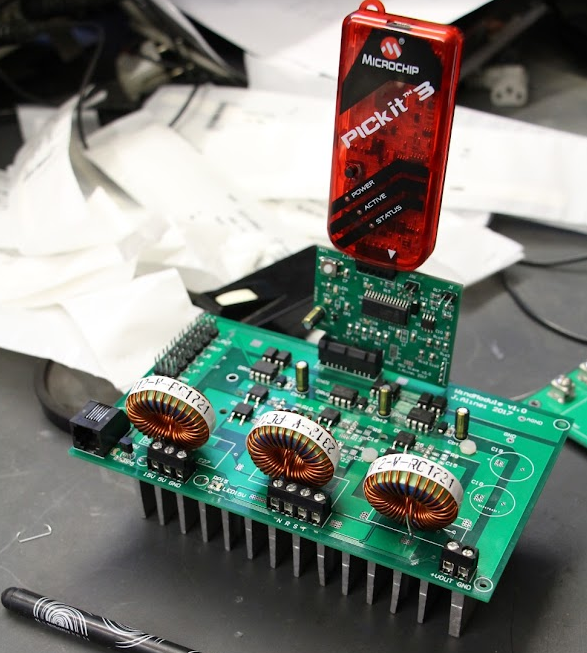
#3 An attempt at making a back to back prototype with pogo pins
On the next prototype we've used pogo pins instead that were providing an electrical contact without constraining the mechanical assembly. It yielded far better results. Two PCBs were mounted back to back - One PCB was the power board, while the second one was the micro-controller board. The stack was screwed together with a 3D printed spacer in between. The low profile spring loaded pogo pins were ensuring the electrical connections.


This new mechanical architecture was far more robust - but it had one severe drawback : thermal properties. The surface mounted transistors had to be cooled from the top which is unconventional. In fact, the most effective way of cooling SMD transistors is to pipe the heat through thermal vias through the pcb and evacuate it from the bottom side. Trying to do differently was not a great idea, the heat had to be piped through the thin layer of top copper (35µm thick) which offered poor thermal performances. (Yes the image is saying the opposite, but no, it was not at all efficient heat sinking).
The second severe drawback was cost. Each contact was about 0.3$ - so we ended up spending about 8$ budget only for pogo pins in our second prototype which was of course unrealistic for mass production.
#4 attempt using castellated holes
Our current design uses castellated holes to connect the micro-controller board to the power stage. All the components are on the top layer to keep the bottom layer solely for heat sinking purpose. We use a standard format of 160mmx100mm, all connectors are on front side and back side of the board.
In the future we will be able to replace the no-tools power terminals with some industrial grade back-plate connectors and fully comply with 19" racking system/ Eurocard format.

At some point we wanted to try flat flex cable solutions (FFC) which is the solution that is deployed in all consumer electronics for board to board connectivity. But we were already skeptical of the resilience of such connectors, they can snap quite easily so we abandoned the idea without testing it.
To summarize our return of experience :
- Going modular is a great Idea but it is not easy.
- The best connector is having no connectors.
- All the connectors attempts were not meeting our expectations and provided poor reliability. Even the expensive pogo pins got a tendency to fail when the spring-loaded contacts were blocked.
- Do not neglect heat sinking !
- Mechanics as to be thought from step 1.
Discussions
Become a Hackaday.io Member
Create an account to leave a comment. Already have an account? Log In.