 Yann Guidon / YGDES
I'm still investigating CC-PBRL (theoretically, these days, but I'll resume practical experiments ASAP).
One unanswered question is a bit puzzling : What is the duration of retention of data stored into a relay coil ?
The magnetic hysteresis is not controlled by the electrical parameters, at least as long as the hysteresis works. It takes energy to reverse the stored magnetic flux so I consider the retention "long". But I have not measured it.
What are the causes of loss of magnetic flux ? As far as I know, the only cause of dissipation is when the core reaches the Curie temperature, which is unknown for this relay.
Another probable cause of "erasure" would be "magnetic interference" : just as a magnetic tape can be erased by subjecting it to high frequency magnetic fieds oscillations, neighbouring relays could affect a coil. After all, they are packed pretty close to each others. The relay's metallic can might help shield the coil but I think it's aluminium (must be verified) which is not a magnetic insulator. At least a magnet doesn't seem affected by the can's material.
Part of the answer might be found in the characteristics of "core memory" arrays, so I am asking my fellows HaDers if they can find estimates of data retention lengths of commercial core planes :-) Does this retention vary a lot at ambient temperature ?
The other question is : how to deal with fanout ?
One way to deal with high-fanout circuits is to increase the voltage so I have now two domains : 3V and 12V (with their respective 2x supplies because electrolytic capacitors need their own bias). But what about the cases where more than 2 (3V) or 8 (12V) relays are needed ?
For the case of 4 relays, there is a solution : use the intermediary 6V rail that is required for the 3V domain, and bias it with the 12V rail. This might be "a bit noisy" though but it solves the problem with no added parts.
The case of 6 relays is rare but 6=8-2 so the string of 6 coils can be connected between the 3V and 12V rails, and biased by the 24V rail.
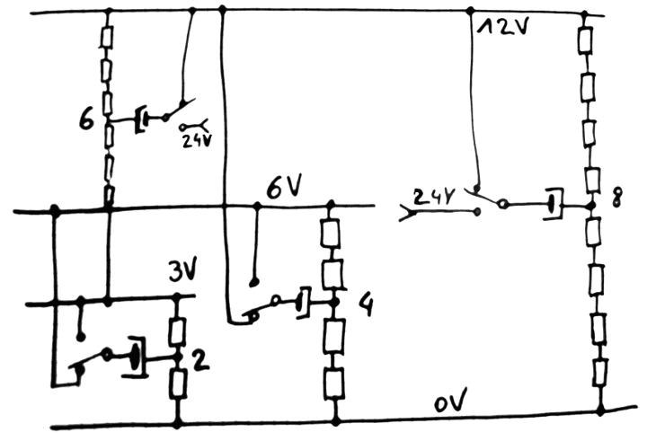
But there are many control signals that require much more than a fanout of 8. Strings of 8 must be parallelled, which brings the question of how to connect them together.
It is possible to create even longer strings, powered with 24V supplies, but then a bias of 48V is required. And even then 16 coils in series is still not enough so why not use the 48V supply ? This would never end, if you follow this logic, and ever higher voltages get used, increasing the stress on the poor coupling capacitors. My stock has 16V and 25V capacitors and I don't want to buy 63V ones...
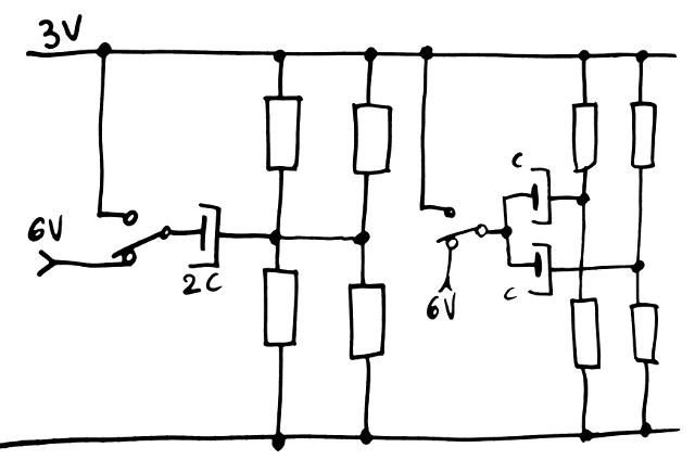
So paralleling is required. There are two solutions : either with shared capacitor, or individual capacitors.
One thing is obvious from this diagram : for a shared capacitor, the capacitance increases with the number of strings. We would rather keep a single capacitor value so the capacitors would be in parallel. This reinforces the case of the individual capacitors.
Another factor is how tying strings in the middle will affect the electrical properties, particularly with temperature drift. The shared capacitor will "average" the characteristics but is it a good thing ? Will this affect data retention times ?
For now, I lean toward the "separate capacitors" version : it's simple, reliable, but hasn't been tested yet.
The question now is the current handling : more strings means more current through the relay's contact. Fortunately the capacitor blocks DC so the relay can easily switch from one state to another without a risk to get "stuck". This proves that CC-PBRL is much better than the resistor-coupled PBRL :-) (Just make sure you have ample and adequate decoupling everywhere)
Discussions
Become a Hackaday.io Member
Create an account to leave a comment. Already have an account? Log In.