 Capt. Flatus O'Flaherty ☠
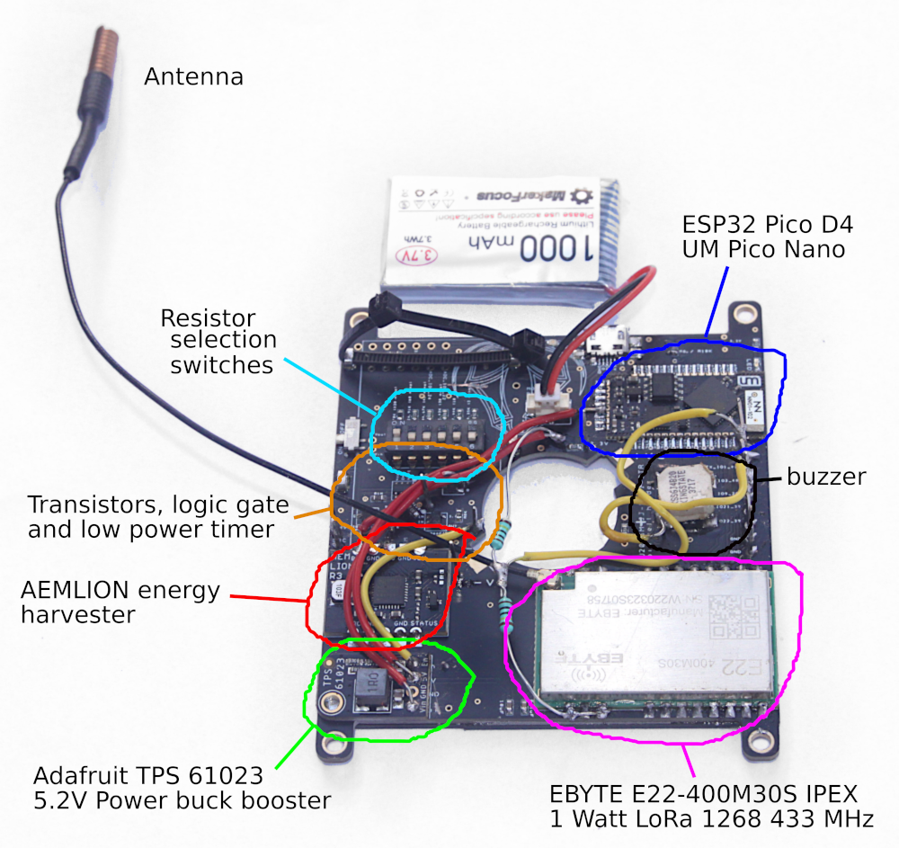
In the latest design iteration there were a few omissions, such as a trace from the battery pad on the harvester to the battery, which is pretty crucial! Other than that, the PCB was perfect, but required a couple of ugly 1MOhm resistors to fly across from the battery +ve to ground to measure the ongoing battery voltage. The original design had the ESP32 powered by 3.5 volts through a small transistor, but this failed as the voltage dropped to 3V and so a few traces on the PCB had to be cut and some red flyer wires soldered on. The yellow flyer wire is just a 3V supply to enable the buck booster. The ESP32 is now powered by the buck booster, using the onboard 5V to 3.3V regulator. It's lucky that the buck booster was there as otherwise the board would be for land fill. The main reason for the buck booster is to power the power hungry LoRa transmitter which needs at least 5V to get a decent transmit power. 5.5 volts would be even better as then the full 1 Watt of power could be accessed.
The general idea of this gadget is that a extremely low power timer chip keeps all the main devices strictly in the 'OFF' state by means of a couple of low leakage NPN transistors and a logic gate. Obviously, the energy harvester is also active and when the battery has a reasonable level of charge the harvester will output a steady 3.3V to the AND gate. The gate waits for the timer to send it's own 3.3V signal and when both inputs are high, it sends a 3.3V high signal to the next transistor. At this point, the main power guzzling devices are activated and, hopefully, some kind of data gets transmitted through the LoRa module. Lastly, the power guzzlers need to be turned off and this is done by simply sending a 3.3V signal to the relevant pin on the timer. All worked fine, BUT this last connection caused an unexpected problem as it turns out the timer can only be set to a maximum of 22 minutes with this configuration. After much head scratching, I realised that the connection that resets the timer must have some resistance or capacitance in it. I kind of proved this by making different connections using the resister switch bank and inferring that there's about 100K Ohms of resistance on the MCU pin. Unfortunately, the trace to the MCU is not accessible and cant be hacked as it's covered with solar panels. As a work around, I used the strangely titled 'Preferences.h' library to save a bootCounter variable permanently into the ESP32 flash memory and count about 21 reboots of the MCU until 6 hours had elapsed. Does it work ..... Yes it does !!! Obviously, there's a small amount of energy loss every time the ESP32 boots up, but it's only on for about 0.5 seconds every 17 minutes. The main thing is that it does not waste energy trying to transmit data every 17 minutes whn a 6 hour time interval is more appropriate for an extreme low power device like this one.
Any casual reader might well be excused for asking the question 'Why not just use the deep sleep mode on the ESP32?' Certainly, this would have been a good solution, but there are some notable advantages as below:
- We can experiment with specialised low power timer chips to find the most frugal one. Currently using TPL5110DDCT, which consumes 35 nA, compared to the ESP32 which uses 10uA in deep sleep. This chip is, in theory, 300 times better than the ESP32, although losses in the transistors and gate need to be taken into account as well. The TC7S08F(F) gate uses 1 uA at 6V, according to the datasheet but could be turned off if the battery falls below 3.6V. No quiescent or leakage current data is available for the transistors.
- We can experiment with low leakage transistors to find the best ones.
- The 5V to 3.3V regulator that seems to be required for the ESP32 can be completely switched off.
- The buck boost circuit that seems to be required to power the ESP32 can be completely disconnected.
- The power to the Ebyte module is completely disconnected due to disconnection of the aforementioned buck booster.
- If the battery falls below 3.6V, there will never be any attempt to power on the ESP32 due to one of the inputs to the AND gate being in the LOW state, which will save energy when most needed. We cant do this using Deep Sleep mode, which would just continue to drain the battery and damage it.
Discussions
Become a Hackaday.io Member
Create an account to leave a comment. Already have an account? Log In.
I'm not sure I correctly understand your comment. Could you say a bit more about your end goals for this device? Meshtastic would 'work' for you in the sense that it's a functional peer-to-peer mesh network that runs on ESP32's (amongst other boards).
Your board might be nice hardware for static Meshtastic repeater nodes
Are you sure? yes | no
Sure. The main features of the board are solar powered, low energy consumption and high transmit power. It's quite easy to use an ESP32 'as is' in conjunction with a low power LoRa module but the power output of the LoRa radio is fairly limited. The high powered LoRa modules that i use require 5.5V to drive their 1 watt onboard amplifier and so it's no longer possible to just hook up a 3.7V lithium ion battery as most other modules like the Helltech LoRa V2 do.
Other considerations include the low power performance of the ESP32, which is currently rated at 10uA and the requirement to have a completely self contained system with no auxiliary solar panels or other modules. All that is required is a suitable battery, external antenna and attachment cable and mounting pole.
This device might work quite well as a repeater node as it could be mounted at the top of a high building or on a short pole attached to a tree top and require little or no maintenance due to being self contained in a weather-proof box.
Are you sure? yes | no
The end goal is to produce a device that Hackers can add their own sensors to, although maybe now it can also work as a mesh node. Possible applications include farm yard security, monitoring bee hives, poly-tunnel and glasshouse monitoring or any application where WiFi or 4G is not available and/or where there is no easy power supply.
Are you sure? yes | no
Nice board. I wonder if it would run Meshtastic? https://meshtastic.org/
A mikroBUS socket might help make it a versatile sensor device https://www.mikroe.com/mikrobus-shuttle-127mm-2x8-pin-box-header-smd-male
Are you sure? yes | no
Thanks for your comment. Meshtastic looks great. I'm trying to concentrate on the low power aspect of the device at the moment and using a peer to peer network to measure the battery voltage at different time intervals. Not tried to add any other sensors yet, although there is plenty of provision on the board to do this using the standard pitch headers. Considering I live in the middle of a small island in the middle of nowhere, what's the chances that Meshtastic would work for myself?
Are you sure? yes | no