 Colin Maykish
About a year ago I collected a few Z180 processors and started doing some research on them. I did the typical new CPU tasks like building a NOP circuit to test the chip, installing and learning some of the software tools and figuring out how to hook up memory. I actually went as far as a having a PCB made up. It worked, but it was a bit of a rush and I abandoed it soon after. All of that to say that I'm not coming at this new Z180 project totally unprepared. Between the proof-of-concept work last year and an additional year of experience with other CPU projects, I feel well prepared to move quickly.
This time around, I decided to forego the NOP circuits or breadboard prototyping and start with hand-soldered boards on the backplane system I've been using on other projects. As I mentioned in the first log, this is not going to be a backplane-based computer, but developing on one for now gives me a lot of flexibility. Today, the first day of the Retro Challenge, was spent building three core boards to get started: CPU, memory, and address decoder on a CPLD.
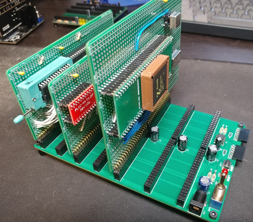
After all that soldering, I had minimal time to do much testing, but I wrote up a basic address decoder for the CPLD and recycled some Z180 code from my previous efforts. I checked for the absolute basics like short circuits and missing connections and then fired it up.
One interesting aspect of the Z180 is the ability to run the system clock, PHI, at different multiples of the input oscillator. By default, PHI is set to 1/2 of the oscillator frequency, but it can be set to 1x or 2x as well. One of the first assembly instructions in my code is to set PHI to 1x the oscillator. On the oscilloscope, I was able to verify that with a 2 MHz oscillator, PHI is indeed 1 MHz on boot and then it jumps to 2 MHz. This is as much verification as I had time for today, but it proves that the CPU is alive and that it can execute code from ROM.
I'm going to try to keep an accurate schematic of this system as I build it in an effort to make PCB design as simple as possible later. Here's what has been wired up so far:
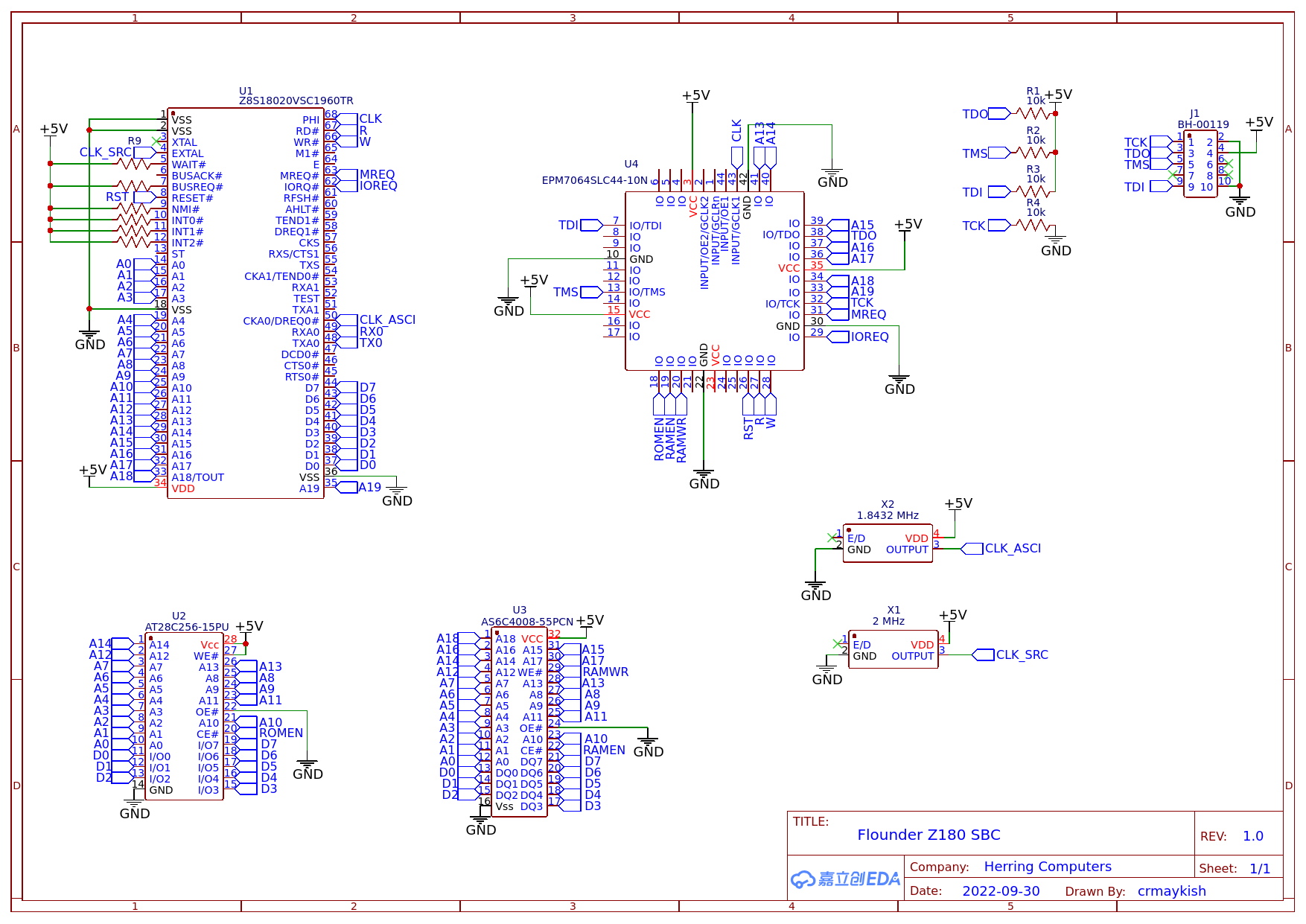
The next checkpoint will be verifying RAM can be read and written and getting one of the built-in serial ports to work.
Discussions
Become a Hackaday.io Member
Create an account to leave a comment. Already have an account? Log In.