 Colin Maykish
Having some GPIO ports available is incredibly useful not only for interfacing with other hardware, but for debugging as well. No matter how bad of a state your code gets in, you can usually find a few instructions to set some LEDs to help you figure out what's going.
For Flounder, the obvious choice for some parallel IO is the Z8420 Peripheral Input/Output controller. This chip was designed for the Z80 bus and so mates nicely with the Z180 as well. The bulk of the time spent today was dedicated to soldering up the board. Adding address decoding for the PIO chip select line and writing some proof-of-concept assembly wasn't much of a problem. My address decoding is pretty crude, the only slight complication is that the Z180 internal peripherals are mapped starting at I/O address 0x00 by default. There is a mechanism to move this I/O to a different offset, but for now it's easier just to map the PIO higher up in the address space. It currently has all of 0x80 through 0xFF to itself, though it only uses four addresses.
The PIO is a simple chip to program. There are a few different modes for each of the two 8-bit ports, but I just want mode 0 (output) on a single port for now. Once the mode is selected, the output port, hooked up to LEDs in this case, is set by writing to the memory location for port B.
To show signs of life, I incremented port B in a loop, counting up in binary on the LED array:
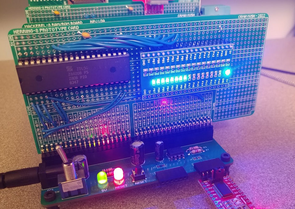
It's hard to tell in a photo, but port B is counting up nicely as expected.
The PIO supports a bunch of other features besides being an output port, but I'll save those for another time. We've got blinky lights, the sure sign of a promising hardware project.
Discussions
Become a Hackaday.io Member
Create an account to leave a comment. Already have an account? Log In.