 Colin Maykish
The good news first: I'm finally starting to grasp the z88dk configuration. I've managed to remove all of the hacky nonsense in my code to work around my lack of understanding of the proper way to do things. Without relying on any custom assembly or my own CRT code, I've got vectored interrupts running as expected. It turns out it's just much easier to store the vector table in RAM than in ROM (I should have learned that lesson from the 68000). Here's the command I'm using to build my monitor program:
zcc -v +z180 -startup=1 -SO3 -clib=sdcc_iy -g -m -o monitor -create-app \
    monitor.c \
    flounder.c \
    ps2.c \
    -pragma-define:CRT_INTERRUPT_MODE=2 \
    -pragma-define:CRT_ENABLE_EIDI=0x13 \
    -pragma-define:CRT_ORG_VECTOR_TABLE=0xFB00 \
    -pragma-define:CRT_ORG_CODE=0 \
    -pragma-define:CRT_INCLUDE_PREAMBLE=0
To summarize: this is building my code against the embedded Z180 CPU target and associated libraries and building a ROM image. It's also taking care of setting the interrupt mode to 2 (vectored interrupts), enabling interrupts at the appropriate time and setting up the vector table high up in RAM at $F800.
The bad news is that it took me many hours of chasing my tail to get to this simple-looking solution. I ended up re-implementing all of the interrupt handling and vector table setup by hand to prove to myself that the software was working as expected. It was. I was still having horrible stability issues when interrupts were on and the LCD display was connected. If I removed either of those pieces, things seemed a little better. I spent some time debugging the address decoder logic and the display controller timing looking for bus conflicts or other issues. Everything seemed fine. After many hours of this, I rearranged some of the boards on the backplane and things were magically stable...
I'm not planning to use a backplane in the PCB design, so this is not the end of the world, but it's a good reminder never to trust the hardware. I'm not 100% sure if the problem is due to reflections and noise on the backplane or if I need to add some bus transceivers between the CPU and everything else. All of my peripherals are low current modern CMOS chips so I'm crossing my fingers that this is just a problem with the backplane and my miles of messy jumper wires.
Once I did some cleanup of the code and convinced myself the system was stable enough to continue, I moved on to wiring up the CH376S. Like the LCD display, this chip is designed with Z80-style 8-bit parallel buses in mind and the pins all map one-to-one. I have some experience using the CH376S on my other homebrew systems, so rather than build all of the software out for the Z180 now, I just want to see some signs of life for now.
My goal is still to get a working version of this computer on a single PCB by the end of the Retro Challenge. To make that schedule work, I'm going to stub out all of the hardware and get it to a proof-of-concept state and then move on to PCB design. While I'm waiting for the PCB to be manufactured and shipped, I'll have some time to work on the software.
Anyway, here's my proof-of-concept testing for the CH376S:
** Flounder Z180 System Monitor **

> ipoke A001 05

> ipoke A001 15

> ipoke A000 05

> ipoke A001 06

> ipoke A000 55

> ipeek A000
AA
Again I was able to use the monitor to communicate manually with the chip. I got enough information to show that the wiring is correct and the communication is working as expected. This series of pokes resets the CH376S and sets it to USB host mode. The final command 0x06 and the following data value 0x55 maps to the CMD_CHECK_EXIST command. It responds with the binary-inverted value that you send it, in this case 0x55 -> 0xAA.
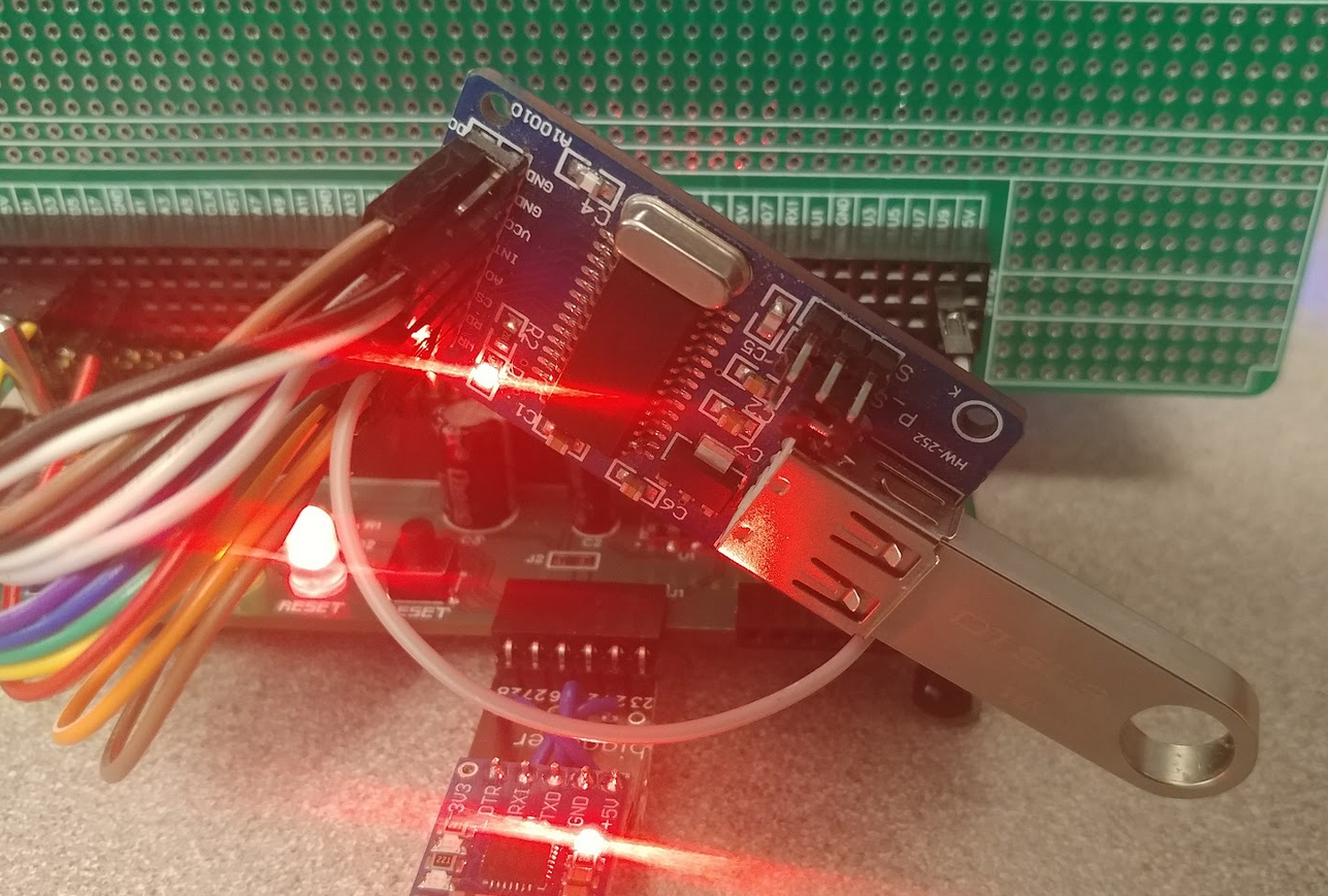
That red LED is off by default, so when it turns on, it shows that the module has initialized correctly following the reset commands.
With that, my initial hardware requirements check list for the first version of Flounder is almost complete. The only other things I'd like to quickly prove out are the MAX232 circuit and connector pin-outs and maybe experiment a little with the power supply / reset circuit.
The PCB design will likely take a few days for a board as complex as this one and the manufacturers will take a week to get the boards to me, so I should have another week before the end of the challenge to bring up the boards. It's a tight schedule, but I think it's doable.
Discussions
Become a Hackaday.io Member
Create an account to leave a comment. Already have an account? Log In.