 doctek
Ordering from the usual suppliers, I got VID2905 motors and X27168 motors. For the controllers, I ordered STI6606z and AX120 chips. These items were ordered from different suppliers. Since they are all very cheap and their performance may not be consistent, this strategy of ordering redundantly from various suppliers is one I recommend.
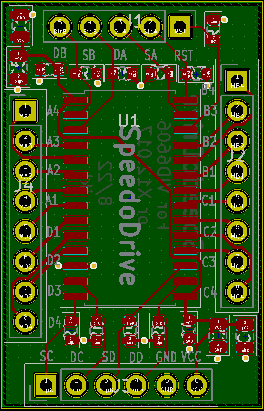
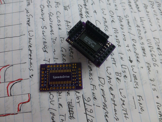
With parts in hand, I studied the data sheets to guide my design. Both controller chips (and similar ones like the VID6606) have the same footprint and the data sheets appear nearly identical. So I designed one pcb to carry the controllers. The data sheets are attached in the Files section. KiCad files and pdfs are also there. Both data sheets state the need for resistors to pull unused inputs to a known level. CMOS doesn't like to have floating inputs! I used 10K pull-down resistors. What this means is that any unused inputs can be safely ignored. The data sheets also state requirements for bulk capacitance. I designed in such capacitance. No further capacitors are needed. By providing these features, my design is fully compliant with data sheet requirements. This is notably superior to simply using a 28 pin SOP generic breakout board. My board may be ordered from OSHPark as SpeedoDrive. The parts placement diagram and paste layer for a stencil are included in the Files. The parts are listed in the Components section.
How to hook up a motor
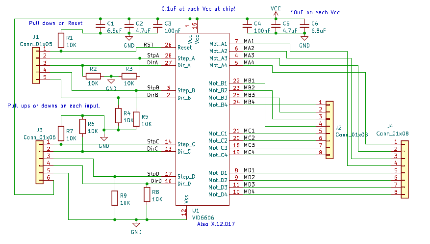
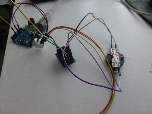
The controller schematic and PCB are shown above. To connect a motor to channel A, hook one coil of the motor to A1 (MA1 on the schematic) and A2 (M2); connect the other coil to A3 (MA3) and A4 (MA4). If you wish to reverse the direction of rotation, switch either pair of wires. That is, move the wire from A3 to A4 and the wire on A4 to A3. Pin SA (StpA on the schematic) is the step input for motor A while DA (DirA) is the direction input. Connect these to digital output pins on the Arduino. The RST pin should go to an Arduino output also. It must be high to enable the controller. Finally, connect GND to ground of the Arduino and VCC to 5 volts. The 5 Volt supply may be from the Arduino if only one channel is to be used. If multiple motors are to be driven, an external 5 Volt supply may be needed. The results look like the picture below.
The Arduino program is ???.ino in the Files section The video shows the STI6606z controller in action in the first sequence. The smooth action is clearly seen. But there is more to the story!
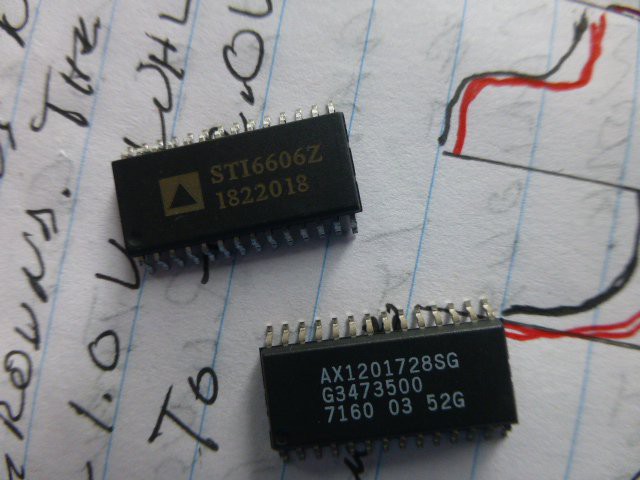
I built two versions of the board: one using the part marked AX1201728SG and one using the part marked STI6606z. I tried both versions with an X27.168 motor and a VID29-05 motor. The parts are shown in the next two pictures. The same Arduino program and hardware hookup was used for all testing.
The rest of the story:
- Using the controller chip marked AX1201728SG, I found that neither of the motors worked reliably. Sometimes, I could get some movement in one direction, but the motor would not reverse. I tried many experiments, including a separate 5V supply and different channels, but nothing helped. I was almost ready to decide the parts did not work reliably! But I kept experimenting.
- Using the controller marked STI6606z, both motors worked perfectly (see video)! So now I believed that both reports of performance were correct: some worked, some didn't. But why? Could I find a smoking gun?
- The two chips were tested using the oscilloscope. I hooked one channel from A3 to ground, one from A4 to ground, and one from SA to ground. At first glance, the drive waveforms look the same.
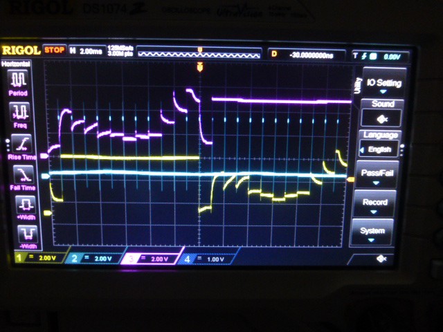
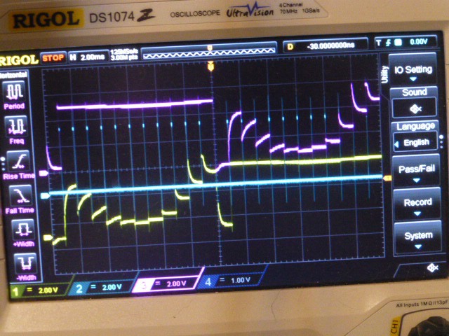
But on closer inspection a clear difference is seen. The low steps from the STI6606 are nearly a volt closer to ground than those of the AX12017! (Ground is indicated by the top arrowhead on the left side of the screen.)
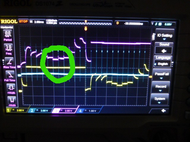
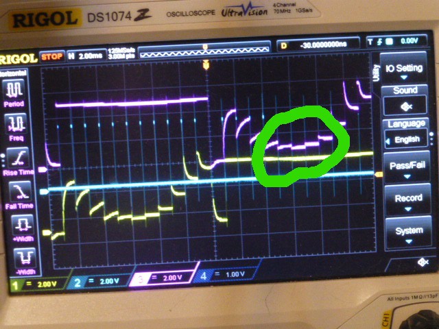
That seems to be the difference between working and not working. Smoking gun indeed! Now the reason why some controller chips work and some don't is understood. Some of the knock-off parts have a process or design flaw. My approach will be to order controllers from various suppliers (they're cheap) and test one of each batch to see which work and which don't. My first choice would be to try ones marked STI6606z, but I don't know if they will be consistent or not.
Note that these waveforms won't happen unless a motor is connected to the chip. You can also connect a resistor in the 180 to 220 Ohm range across each coil driver. Nice crisp steps are seen since there is no inductance in the circuit.
The Arduino program for the STI6606z/AX1201728 controller is attached as UnoAccelStepperSTI6606z.ino. The program uses the AccelStepper library to provide step and direction signals to the controller. For testing, a pot is used to provide a variable signal as input. Pot readings are averaged and must move out of a dead band to cause cause an update. The readings are taken every 1/10 second. Target position is updated if appropriate. The run() function is continuously called to move the motor.
A video of the resulting movement is linked and is discussed below.
Using an a4988 driver
The a4988 stepper driver is often mentioned in forum posts as being suitable for the VID29/X27 motors. The a4988 driver is designed for stepper motors needing around 1 Amp of drive current or less. They are massive overkill for the VID29/X27 motors. However, they are cheap and a lot of folks own them and want to use them for these little motors. So, can it be done safely and what are the results like?
Pluses for the a4988:
- no need to build a board - easily available
- works consistently (no worries about flaky suppliers)
Minuses for the a4988:
- requires separate 8V to 35V supply (I used 12V)
- single channel board is about the size of my controller board that can handle four channels
- needs 47u to 100u cap of an appropriate voltage rating - 47u is enough for these small motors
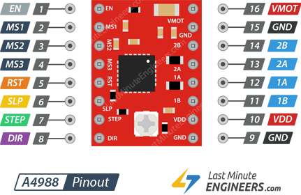
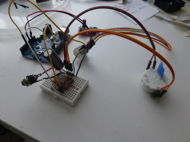
Hooking up a motor is simple: The picture above shows the two motor coils hooked to the 1A/B and 2A/B drive pins from the a4988. Step and direction are tied to appropriate Arduino pins. Sleep is jumpered to Reset, the Enable pin is not used (although it could be) and pins MS1 to MS3 are tied appropriately to control microstepping. Consult the data sheet for more detail and see Last Minute Engineers if you need more hookup detail.
- All MS pins are no connect for full step mode (they are internally pulled low)
- MS1 is tied high for half stepping
- MS2 is tied high for quarter stepping
- MS1 and MS2 are both tied high for eighth stepping
The first step is to use the motors safely. That is, without supplying excessive current. All that's required is to turn the a4988 reference voltage to its minimum value. This worked fine for my motors. They did not heat up and did not make any excessive noise.
To test the a4988, I used the UnoAccelSteppera4988_VID2905.ino Arduino program which is nearly identical to the program described above. It also works with the AX1201728 motor. This program makes it easy to test the a4988 driver with various microstep settings. Change the variable indicated in the program to select the microstep setting that matches your hardware setting.
Results of testing the STI6606z and the a4988 in various microstepping modes are shown in this video
. The video begins with movement produced by the STI6606z. This controller moves the needle very smoothly. I was using the Arduino program UnoAccelStepperSTI6606z.ino and turning the pot by hand while holding the camera. The small jiggles at the end of a movement are due to the pot settling to a final value.
The next sections of the video show the a4988 controller in various microstepping modes.
- Full step mode gave jerky movement
- Half step and quarter step both gave smooth, satisfactory movement
- Eighth step mode gave somewhat jerky movement
Note that the sounds from the motor change with the microstep settings. Quietest with the STI6606z, then louder with full step and eighth step, and fairly quiet with half and quarter step. The sounds were not recorded rigorously, but just with the camera mic in the same position each time.