 Real Solar Cars
Installing a moderately sized solar array on a vehicle’s roof can collect enough energy to drive 5 to 10 miles a day. When compared to the 37 miles a day that the average American drives, it may seem insignificant. Everyone wants to say the glass is three quarters empty. But we should think of it being one quarter full. A 25% reduction in vehicle “energy consumption” is huge.
Many areas still do not have good EV charging infrastructure. Workplace chargers would be ideal for managing the Duck Curve. The EVs could charge during the day from the plentiful solar energy. But many companies are still not willing to install chargers. A vehicle mounted solar charger will work anywhere there is sun. This is a practical and tangible way for drivers to reduce their environmental impact. And it has the potential for an economic return on investment by supplying clean, low cost electricity directly to the vehicle. The cost of a solar charger might be offset by choosing not to install a home EVSE for vehicle charging. Or it could allow an urban dweller who does not drive much to get an electric or plug-in hybrid electric vehicle even if they can't install an EVSE.
This project aims to add solar charging to a Chevy Volt in a manner that does not require any special work by the driver. Well, it will need to be parked in a sunny location. But the driver will not need to plug a cable into the J1772 port for charging like the majority of solar car projects. This project also avoids an additional battery for temporary energy storage and the losses from multiple AC to DC conversions.
Project Progress
☑Solar array mounted on vehicle.
☑IOT data logger.
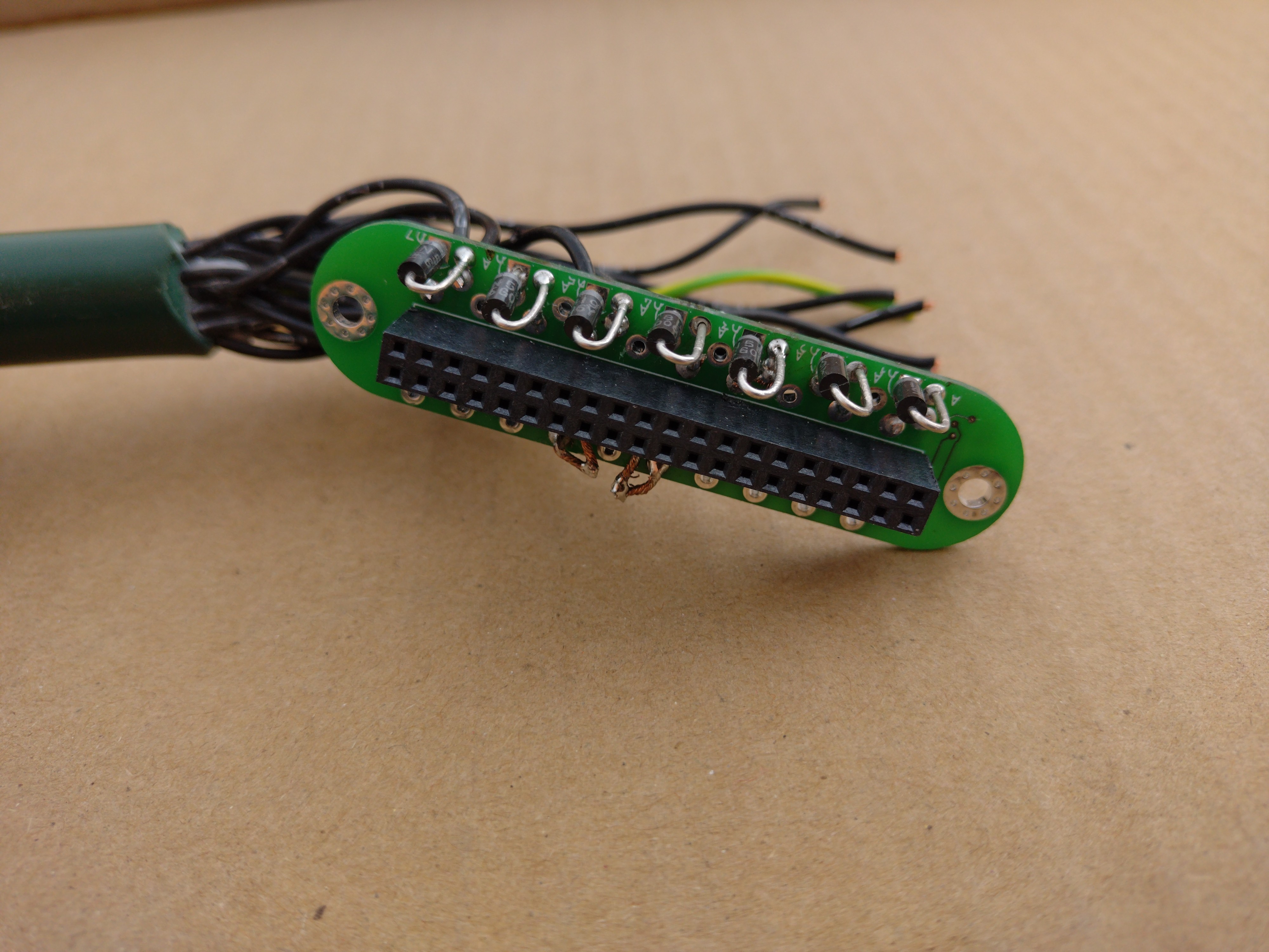
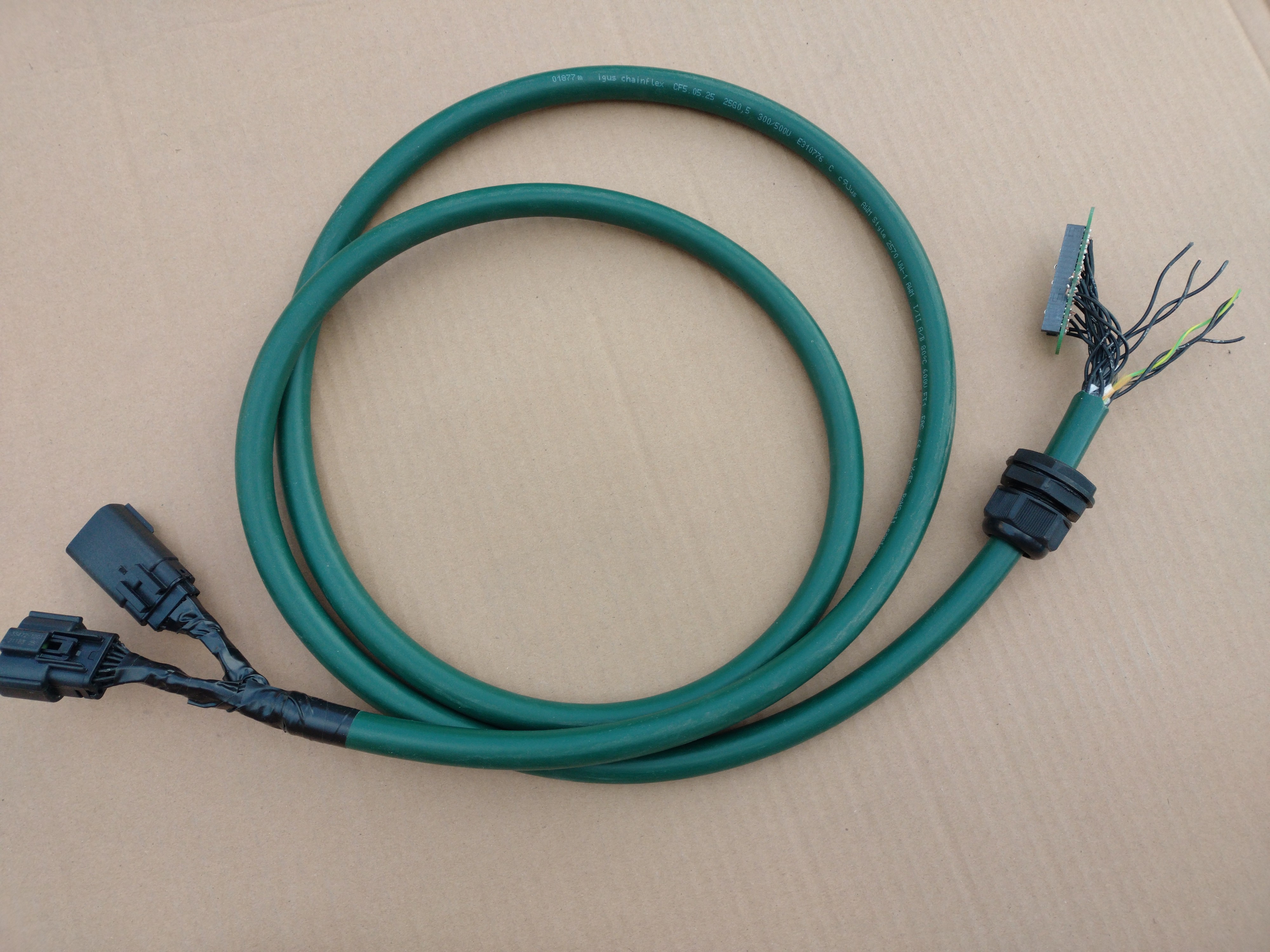
☑High voltage DC-DC charge controller.
☑Charging while parked.
☑Maximum power point tracking
☑Also charge the 12v battery during the day.
☒ Relay coil economizer. Currently disabled due to malfunctioning in the morning.
☑Automatic switching between charging during the day and low power standby mode at night.
Future Directions
☐Avoid check engine light without manually switching off charger before driving.
☐Charging while driving.
☐Charging while charging. (Combined grid and solar charging)
☐Larger and/or more aerodynamic solar array.
Licensing
The DC-DC converter firmware source code is licensed GPL v3. Some of the underlying libraries whether written by myself or others are released under MIT license.
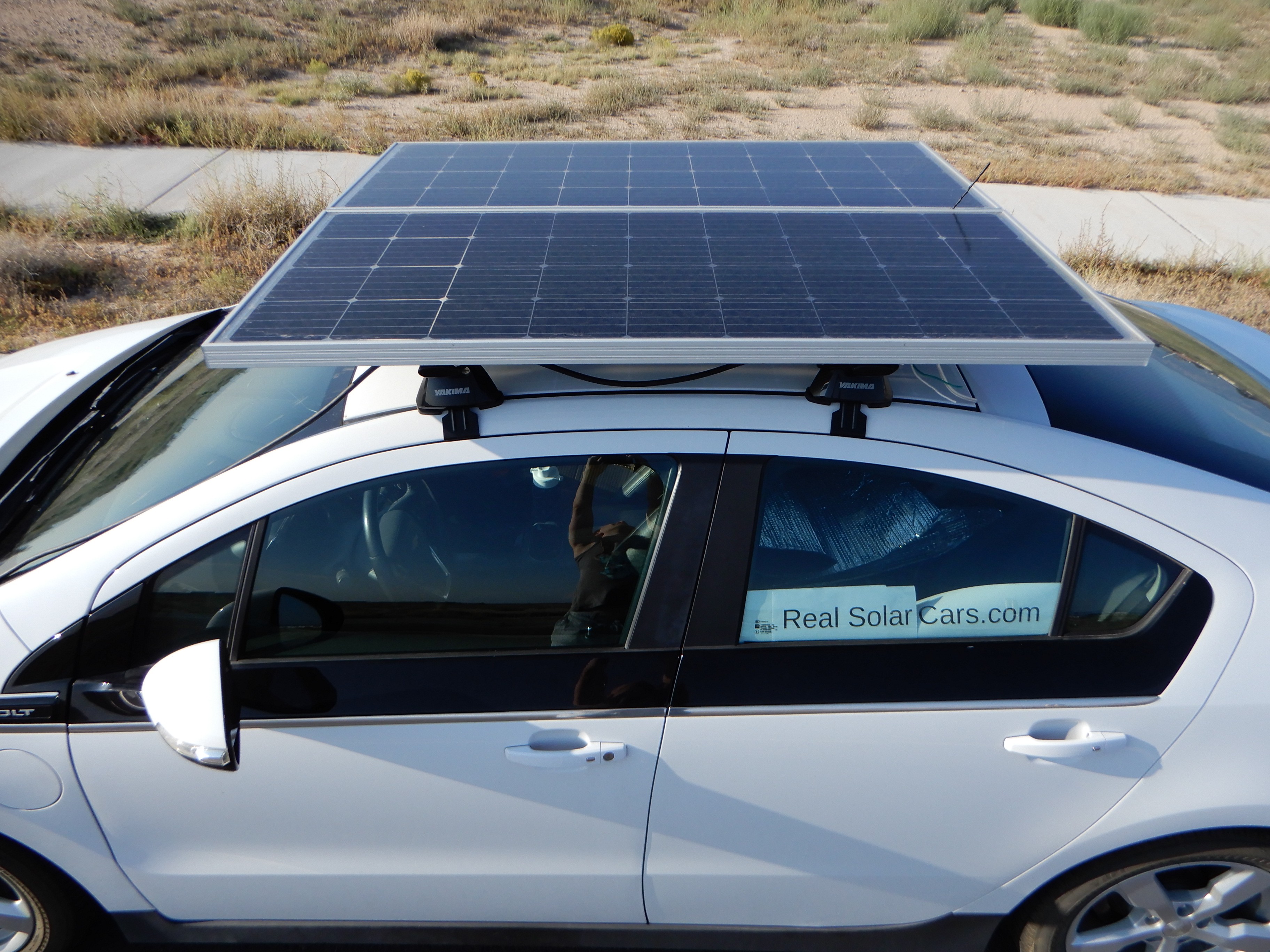
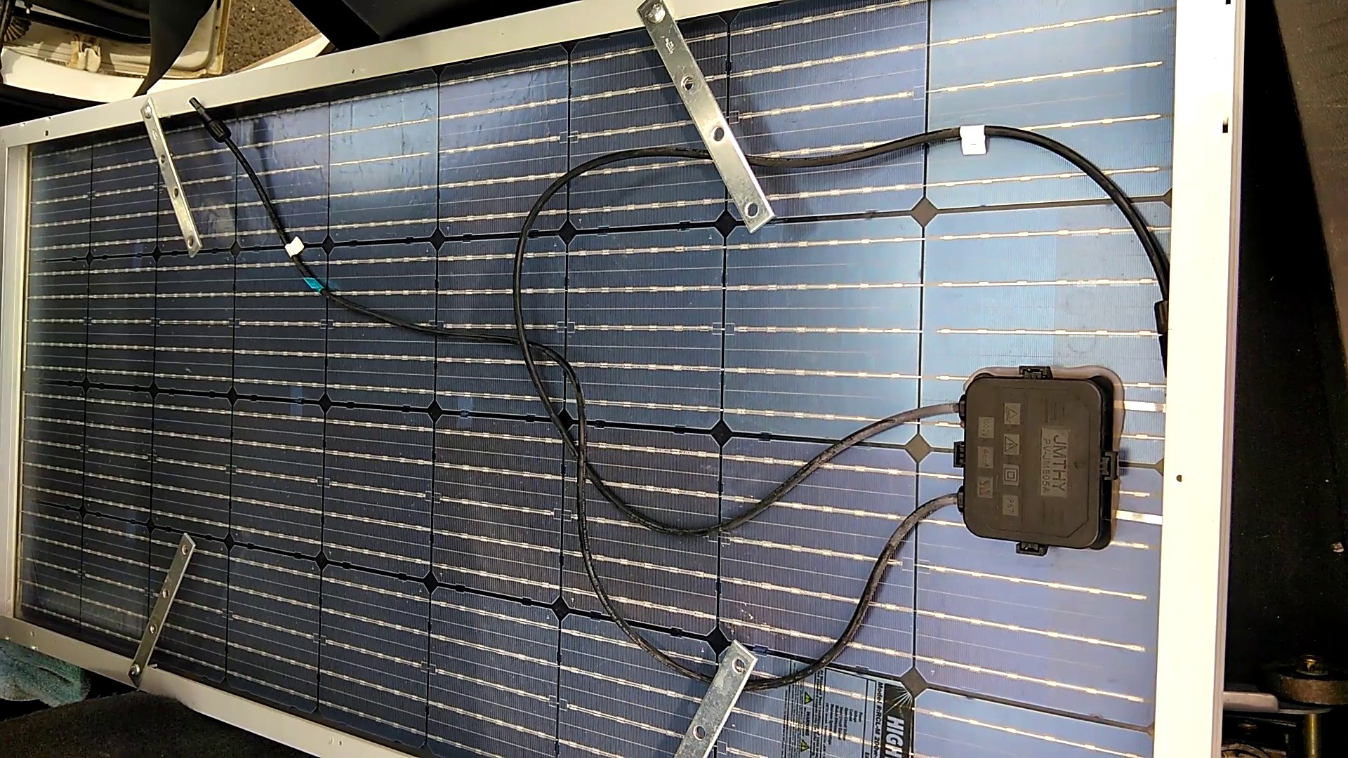
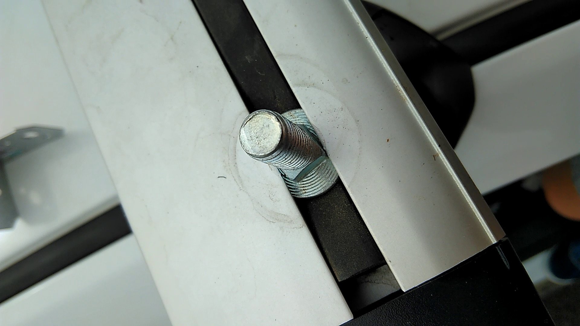
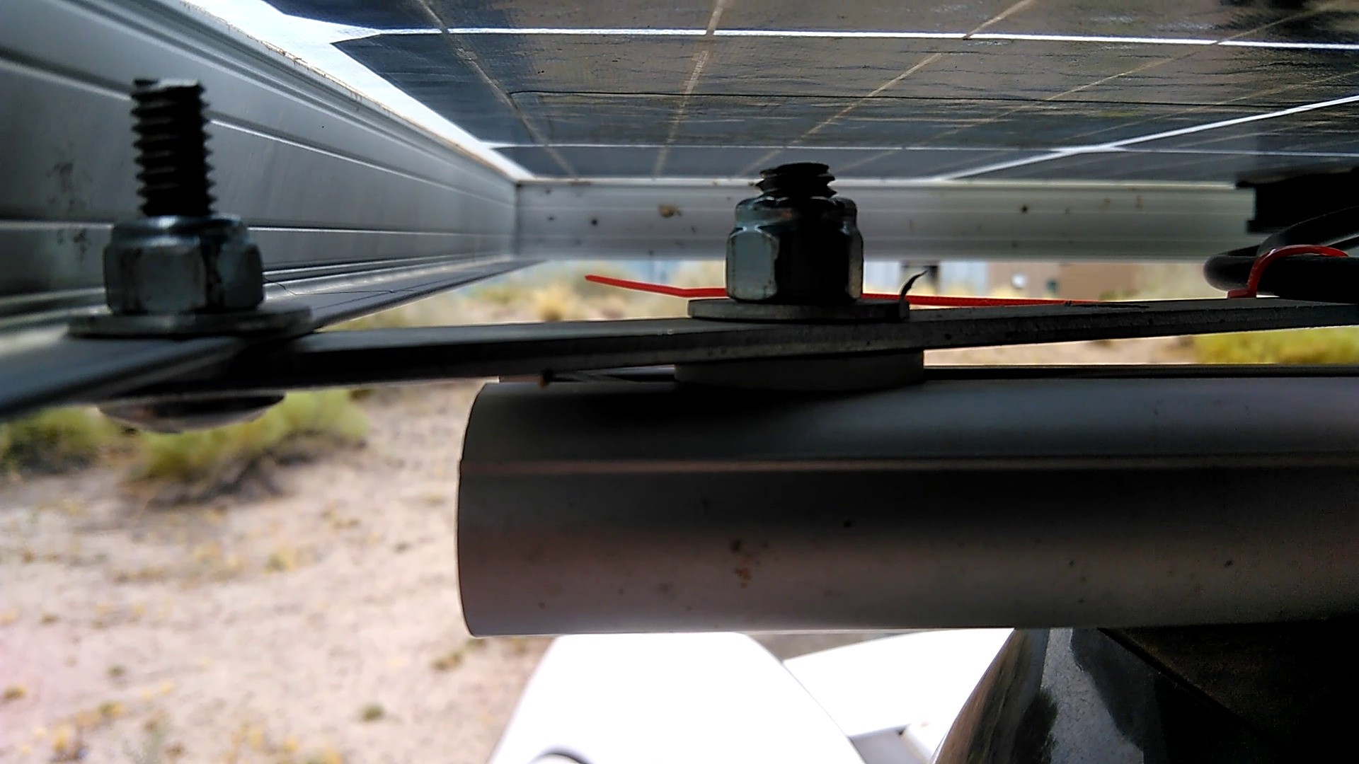
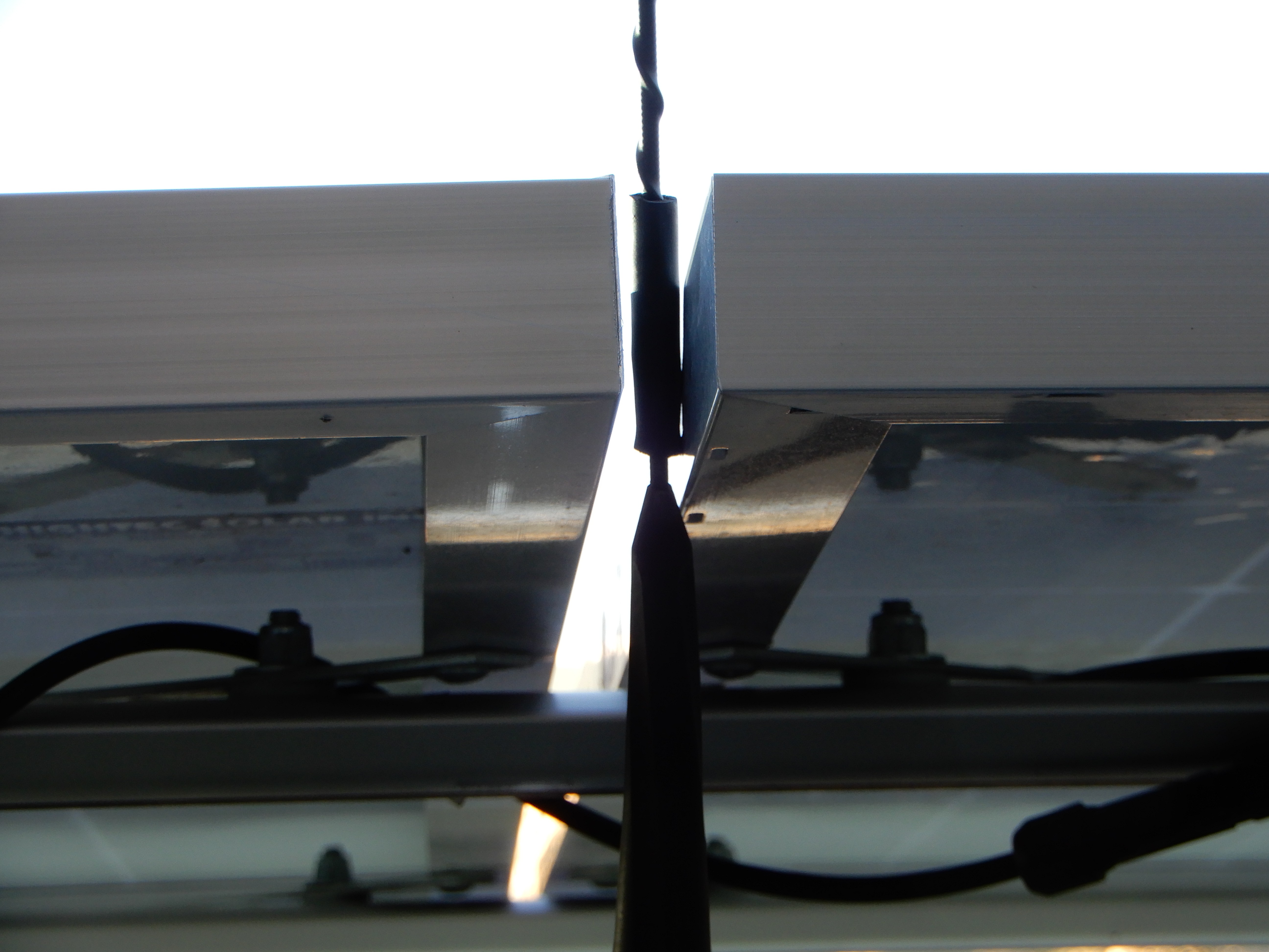
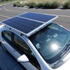
The roof mounted solar array is nearly the maximum size possible before it starts to interfere with normal vehicle usage. The car currently has Hightec Solar 210w panels. (200w bifacial shown) Radio reception, especially satellite, is compromised. The rear hatch can be opened without interference. The solar panels are barely visible through the windshield when seated in the driver's seat. This solar panel setup should not be considered ideal. It was just an easy way to get a good array mounted without permanent vehicle modifications. That was important at the beginning of this project when it was uncertain whether the DC charging would be possible.
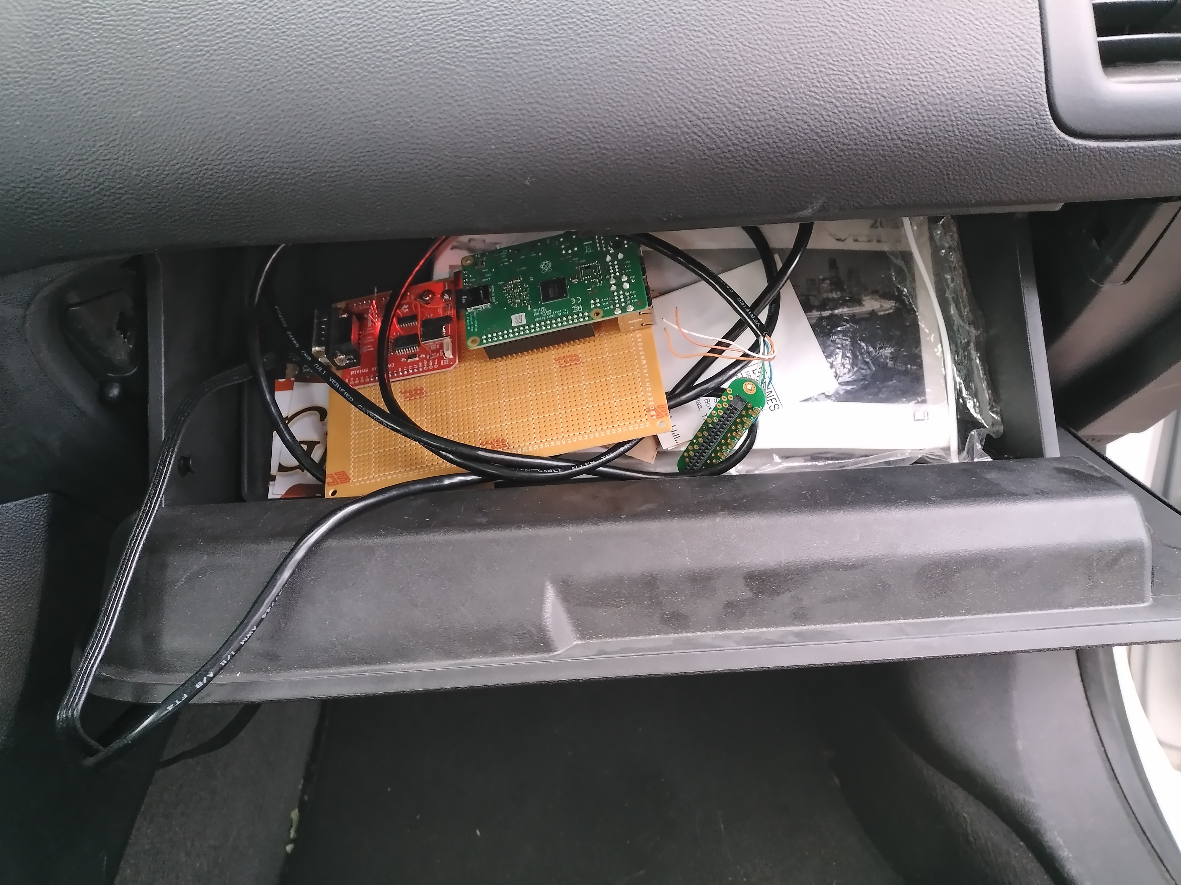
A Raspberry Pi receives data from the high voltage management CAN bus and uploads it to https://realsolarcars.com/?stats
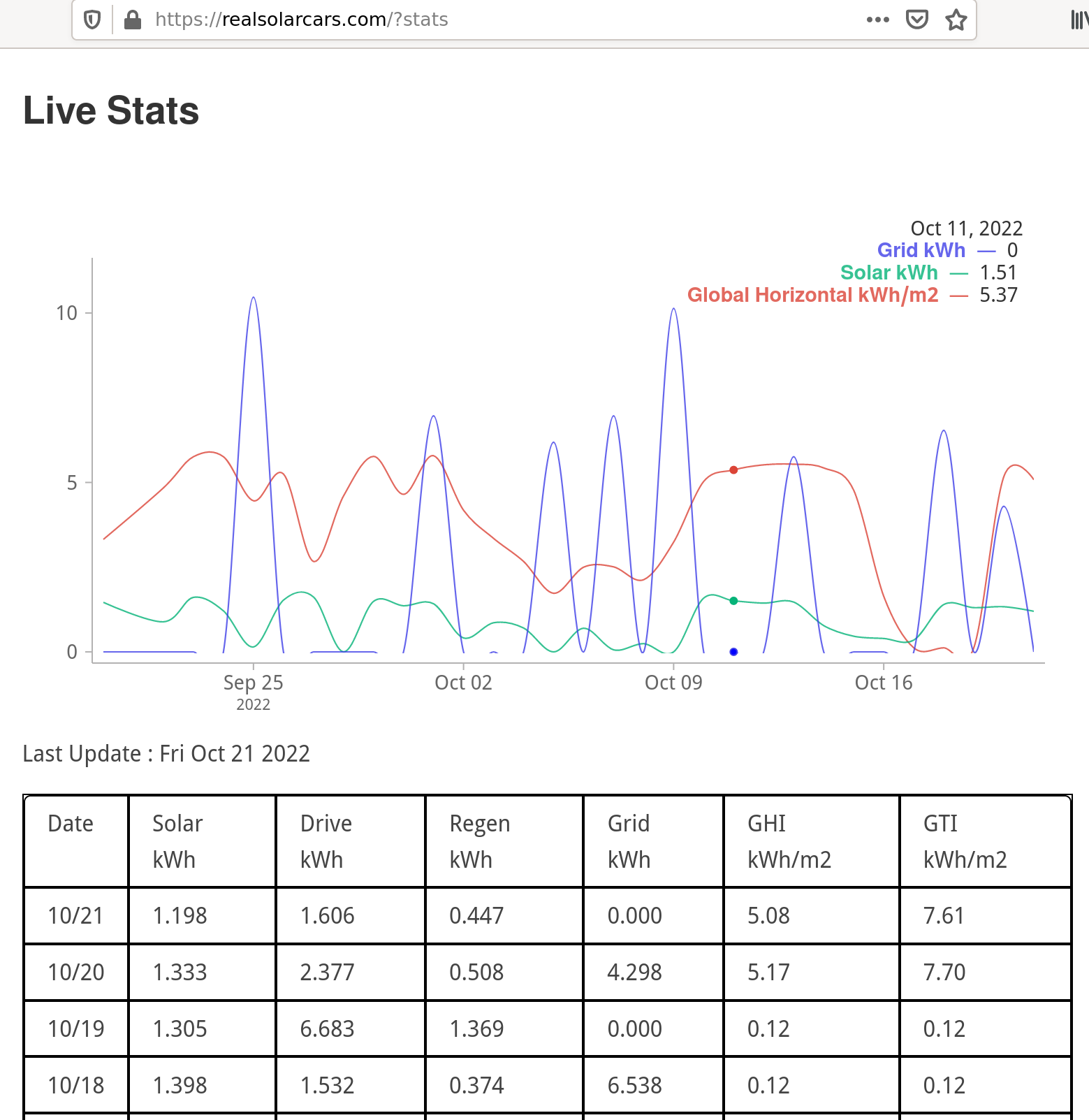
The solar energy collected should correlate with Global Horizontal Irradiance. The GHI is measured at a test station about 10 km away. Sometimes the charger may be down for maintenance or rejecting energy because the battery is full.
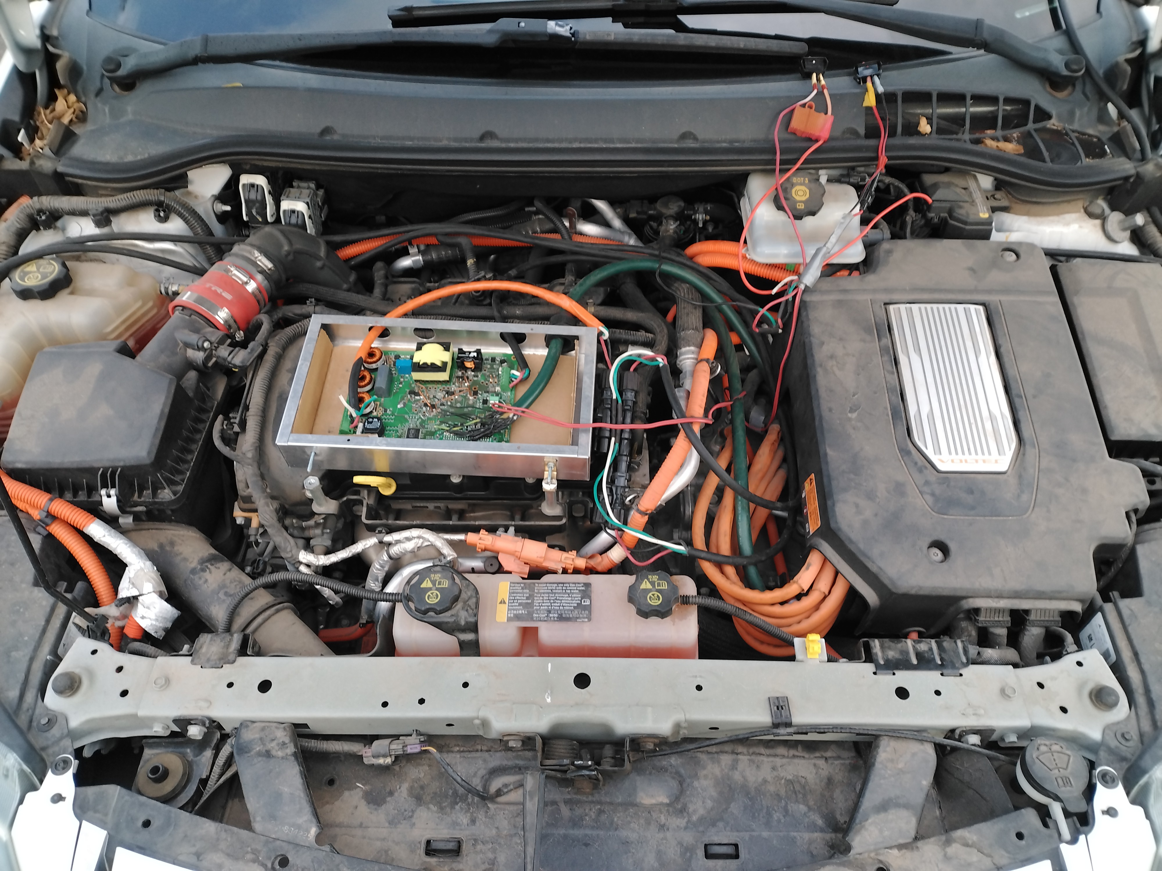
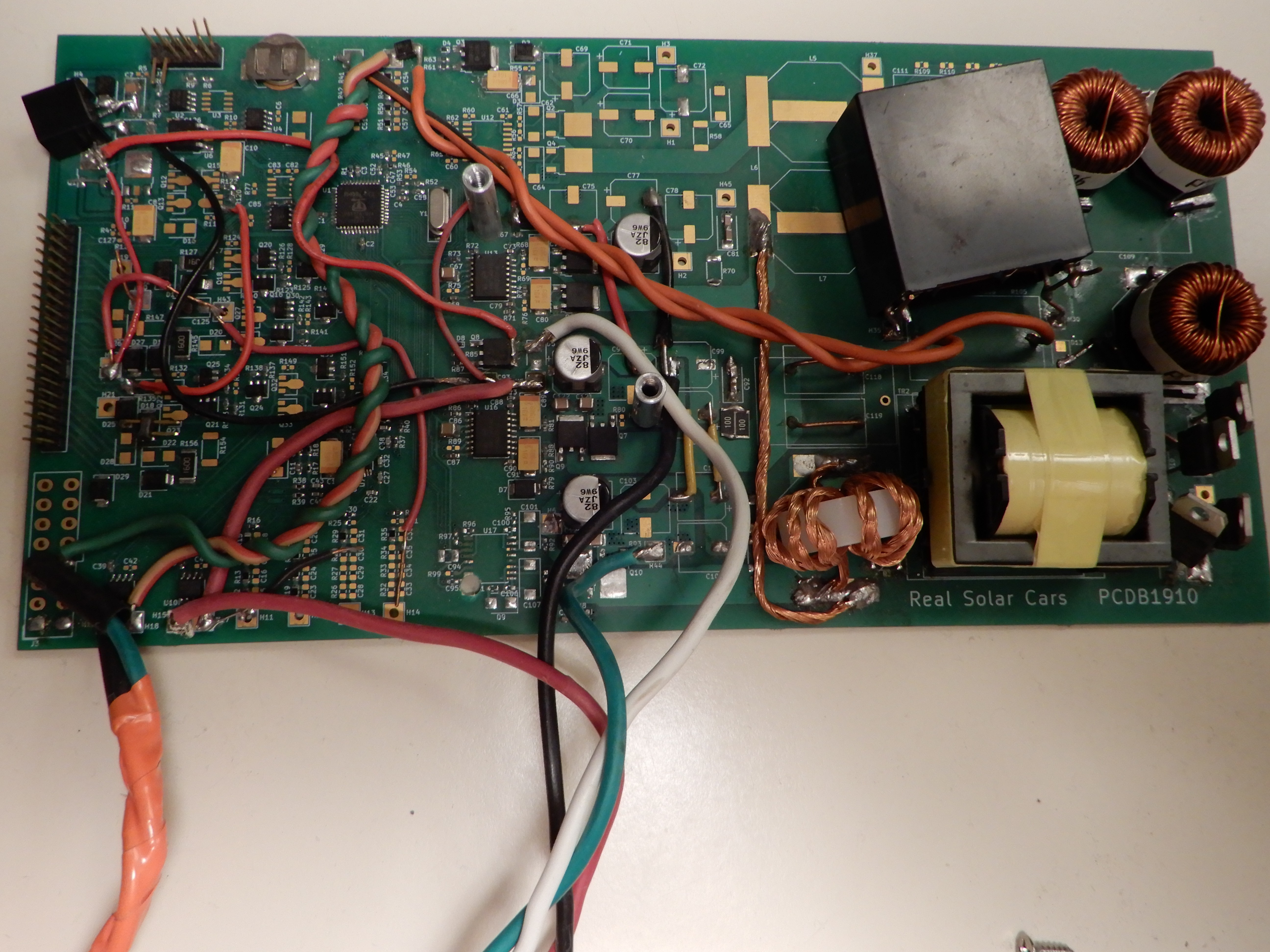
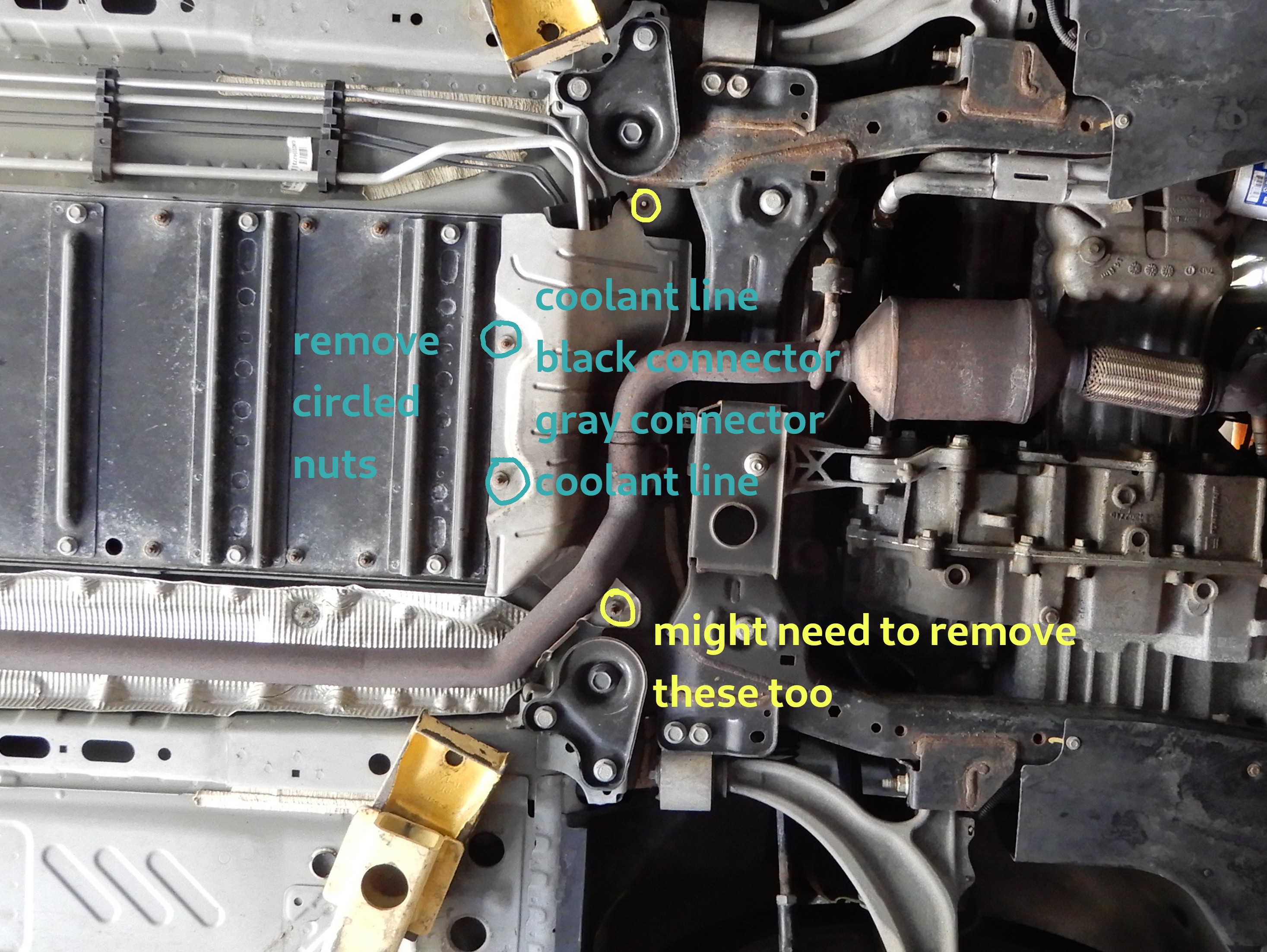
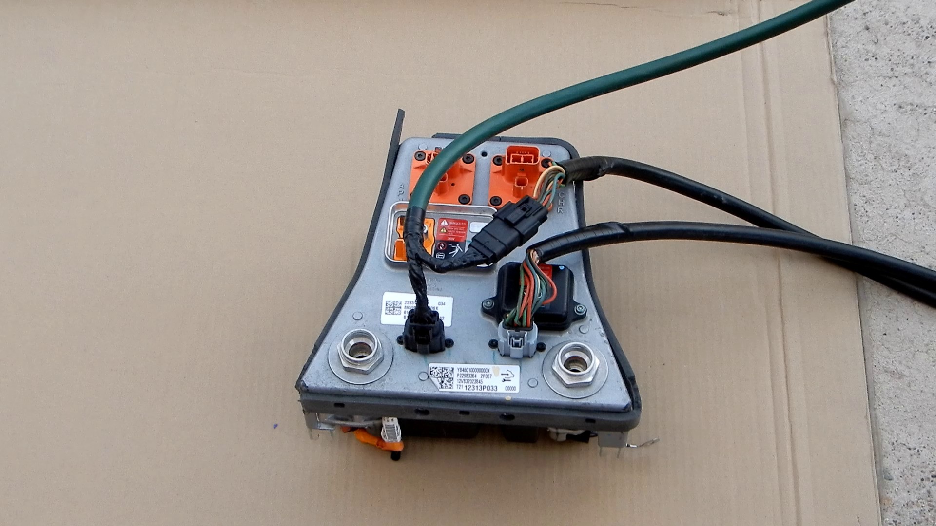
Under the hood is not the ideal location for the DC-DC converter, but it is easy to access and makes for good photos. Two manual shutdown switches are accessible with the hood closed.
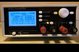
Specifications
Input: 30-43vdc, MPPT intended for 72 cell solar array, should work with 60 cell panels but may not reach maximum power point at high output voltages.
Main Output: 300vdc-400vdc 1A, maximum continuous power about 300w, CV/CC modes, isolated
Aux Output: 13.8vdc 3A, CV/CC...


 Manuel Tosone
 Dan Julio
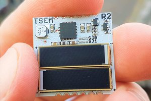
 Jasper Sikken
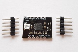
I am proposing to purchase an EV in 2023 and want to charge it DC-DC from a 6 KW solar array dedicated to car charging. Can you help me out with such a converter that I can hang on the wall in the garage and plug into an existing port on the car?