Close
0%
0%

Not-so-smart capacitive discharge spot welder

Portable spot welder that doesn't need microcontrollers, uses recycled industrial thyristor and mostly off-the-shelf components

Similar projects worth following
In this project I designed and built a prototype of USB-C powered capacitive discharge spot welder. It can be used to weld nickel strips to battery packs. This allows re-building battery packs for various devices, especially ones that are no longer maintained by the manufacturers. This spot welder, unlike many available DIY projects, doesn't need a microcontroller to work: the welding pulse is triggered using relay module and a timing capacitor. Welding current is switched with an old recycled industrial thyristor module. Pulse energy can be adjusted with a potentiometer, which changes the voltage of capacitor bank. Capacitors are charged with a step-up DC-DC CC/CV converter and USB-C PD connector (a regular barrel jack can be used instead, if one prefers). Welding probes are connected with XT90 connector. Welding pulse is triggered with a button attached directly to one of the probes.

Overview

I have built a relatively small USB-C powered capacitive discharge spot welder, which can be used to build battery packs for various devices and avoid throwing old devices out just because it's not possible to buy an original battery anymore. I tried to design this spot welder in a bit different way than other spot welders.
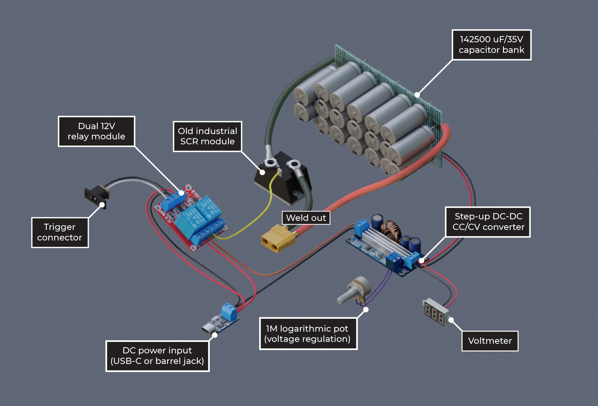
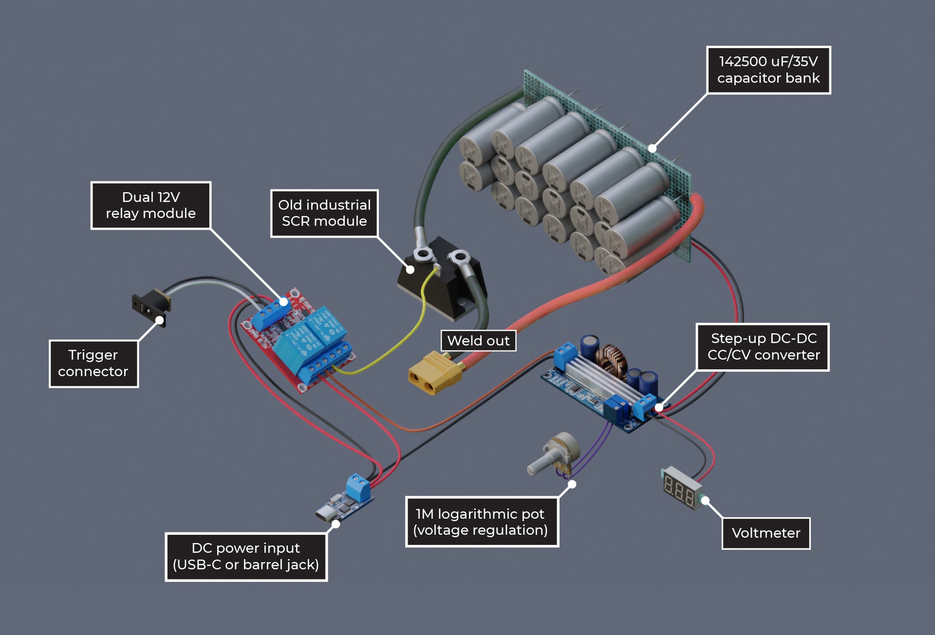
Exploded view of the internals of the spot welder.
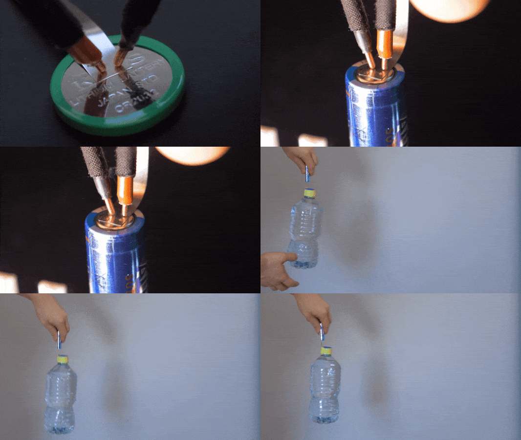
Welding and testing the strength of welds made with a prototype of this device.

The challenge

1. I wanted this spot welder to be relatively safe to use and safe to store. Other spot welders often use car batteries, microwave oven transformers, high-current li-po battery packs or supercapacitors as power source. All of these things seemed to be very powerful and somehow scary to me, so I decided to use an capacitor bank made of regular electrolytic capacitors. These capacitors can store enough energy to make a spot weld, but not much more than that, and there is less of an risk of something bad happening in case of a short circuit.

2. I wanted this device to be fairly easy to build and avoid the need to use custom PCB. Therefore I created it in a modular manned, and chose to use an old industrial SCR module to switch the welding current, off-the-shelf relay module with slight modifications to time the pulse triggering and charging right, step-up converter module with potentiometer added to control the pulse energy and USB-C PD trigger module (optional) to allow powering the welder with powerbanks.

3. No microcontrollers: a button, a panel voltmeter, a potentiometer and a relay module with timing capacitors should be enough. Might help a bit in times of silicon shortage.

4. I wanted it to be compact. I made a custom 3D printed panel and packed everything tightly, but in a rather tidy manner into a plastic case. I didn't want to use a bulky footswitch, therefore the triggering button is placed right on the welding electrode, easily pressed with a finger.

What to do next

At the current stage, this spot welder uses mostly off-the-shelf modules and does not use a custom PCB. This is exactly what I aimed for and probably the most cost effective way to build this device. However, an ability to build it from scratch would also be nice, because it would allow a greater degree of customization of the device, and possibly making it even smaller. Therefore I am in the process of creating a schematic of this spot welder using discrete components to replace the relay module and step-up converter board.

Initial tests already have shown that this welder is capable of creating usable welds of nickel stripes, but I need to do more tests with various voltages and strips of different thickness.


Currently this spot welder uses automotive grade Nichicon capacitors. It would be a good idea to check the feasibility of using cheaper capacitors, and test if it's better to use higher voltage ratings, or higher capacity.
JPEG Image - 760.52 kB - 07/16/2023 at 13:35

Preview
Download

Standard Tesselated Geometry - 123.91 kB - 10/06/2022 at 21:34

Download

simple spotwelder schematic_v2.jpg

Simplified schematic

JPEG Image - 1.14 MB - 10/06/2022 at 20:06

Preview
Download

  • 1 × HW-279 dual 12V relay module
  • 1 × T90RIA120 thyristor module or similar second-hand industrial SCR
  • 1 × Step-up DC-DC CC/CV converter (XY-SJVA-4)
  • 19 × Nichicon UBY 7500uF/35V capacitors (or similar)
  • 1 × USB-C PD 12V trigger module (or barrel jack as cheaper option)

View all 15 components

  • Pulse oscillogram

    Wojciech "adalbert" J07/16/2023 at 13:42 0 comments

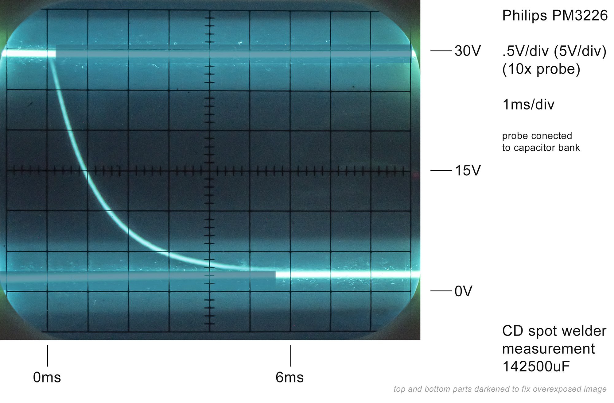
    I managed to capture oscilloscope image of the pulse with an old analog Philips PM3226 oscilloscope. It was a bit tricky, as analog scope don't have digital storage capabilities, so I put a camera in long exposure mode and tried to capture the trace. I measured the voltage drop in DC mode. It worked, and the observations are as follows:

    • Capacitors are discharged in 6 milliseconds
    • voltage drops in half within 1 millisecond
    • minimum voltage doesn't go to zero, but to around 2V (that's because of SCR threshold voltage)

    The probe was connected to the capacitor bank as that was the simplest thing to do. The test was done while spot welding two nickel strips. I guess I could also measure the voltage drop across the welding lead.

    If I get the math right (I entered discharge time of 0.001s from 30V to 15V into this calculator https://www.digikey.com/en/resources/conversion-calculators/conversion-calculator-capacitor-safety-discharge and got 0.01012418ohms) the pulse should be close to 3kA.

  • Video with commentary

    Wojciech "adalbert" J11/06/2022 at 16:24 0 comments

    The video with commentary is finally ready. It shows how does this spot welder work and how to build one:

  • Assembly

    Wojciech "adalbert" J10/08/2022 at 12:31 0 comments

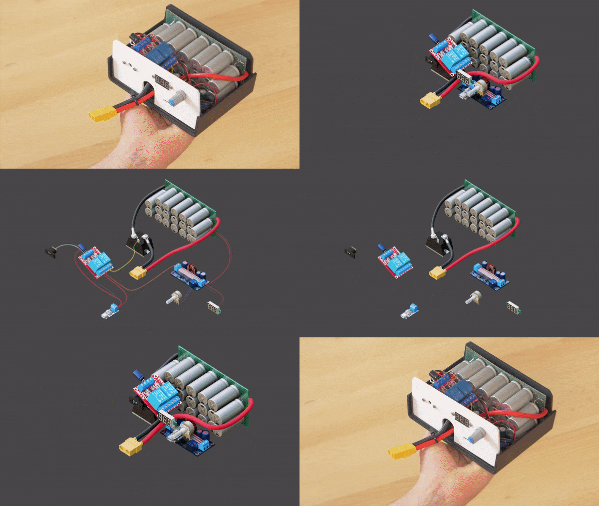
    This animation shows how the spot welder components are packed into the case:

    I used a 3D printed panel (white part, STL files are included in Files section) and a generic plastic case (150mm x 110mm x 70mm model 'Kradex Z3W'). The modules are held with M2.5 or M3 bolts and nuts, and M5 bolts were used to mount welding cables on SCR module.

    Depending on your region you may need to use a case from different manufacturer and make some adjustment to the STL files. You can also make a case of your own, or even use the spot welder without a case.

  • Animated circut

    Wojciech "adalbert" J10/06/2022 at 20:53 0 comments

    I created an interactive animation of a simplified version of the circuit using https://www.falstad.com/circuit/ website.  It shouldn't be treated as an accurate simulation, but it shows the general idea about how the welding pulse is triggered and how capacitor charging and discharging happens.

    You can open the circuit in your browser by following this link: https://www.falstad.com/circuit/circuitjs.html?ctz=CQAgj...

    Step-up converter module is ommited here.

  • Initial welds

    Wojciech "adalbert" J10/06/2022 at 16:02 0 comments

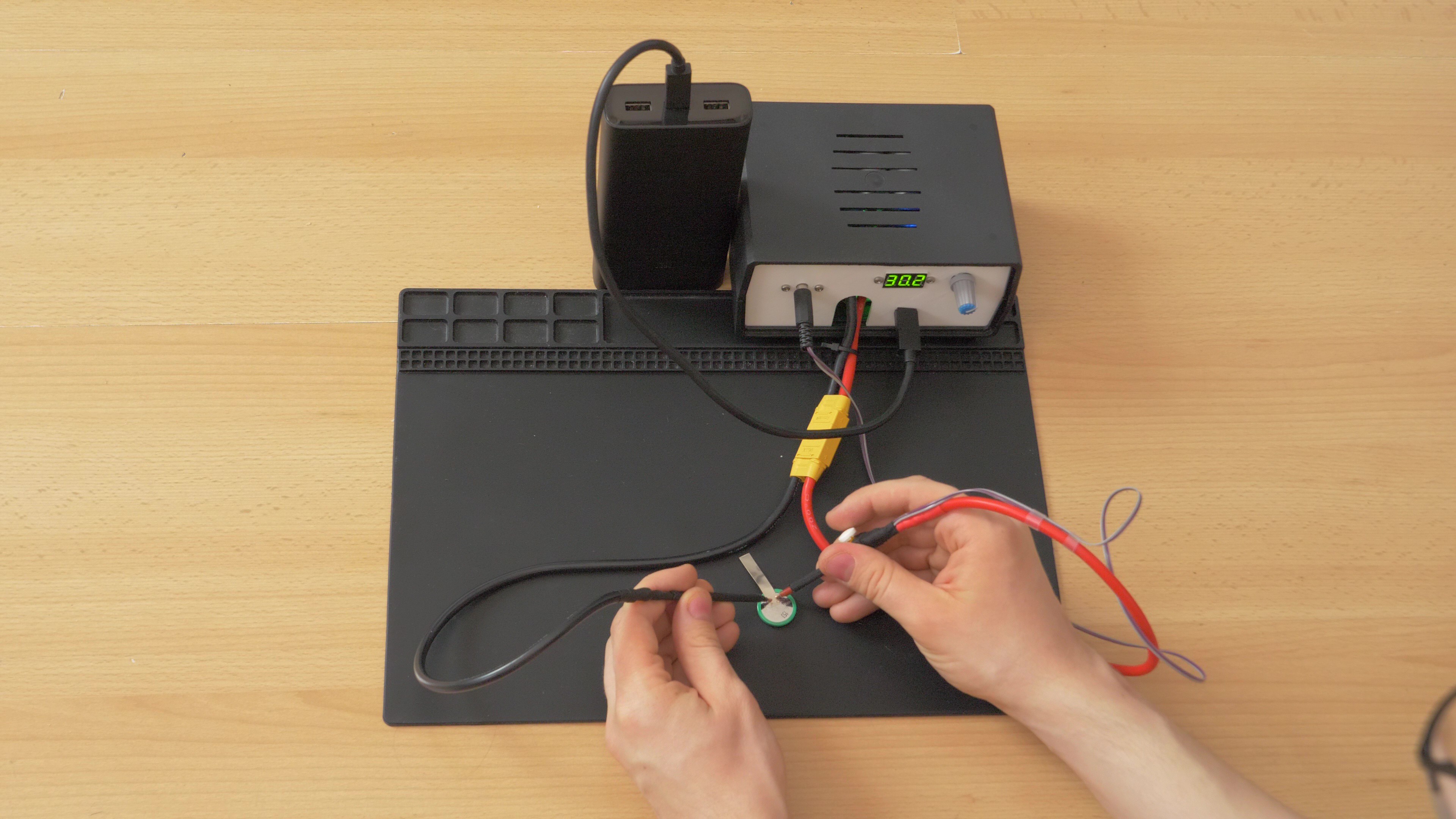
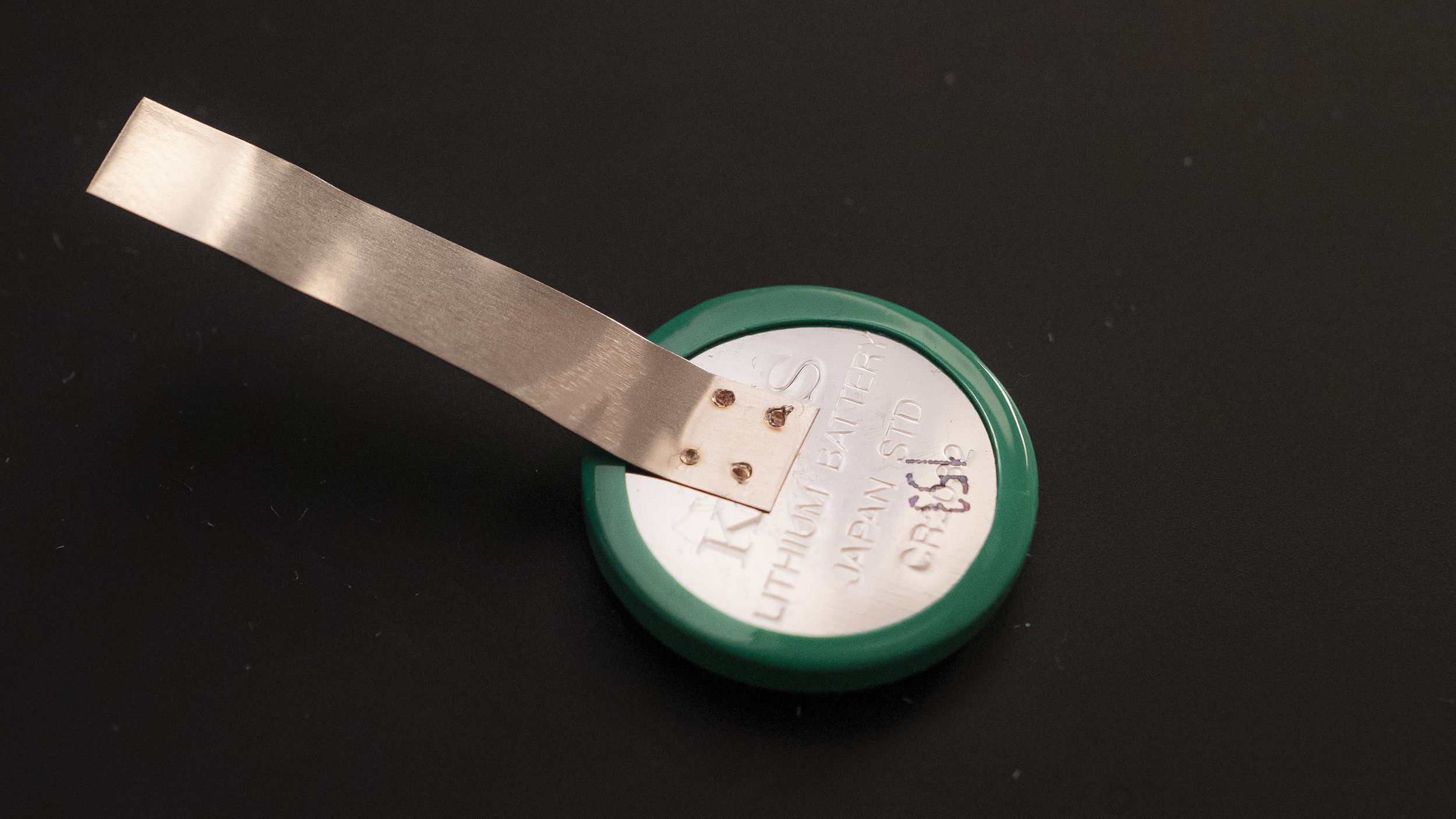
    I did some initial test welds with old AA cells, old coin cells and 0.1mm thick nickel strips. I started with almost maximum voltage (30V), but it's probably more than needed for 0.1mm nickel strips. This spot welder certainly has enough power to serve its purpose. I will need to find optimal voltage settings for various nickel strips.

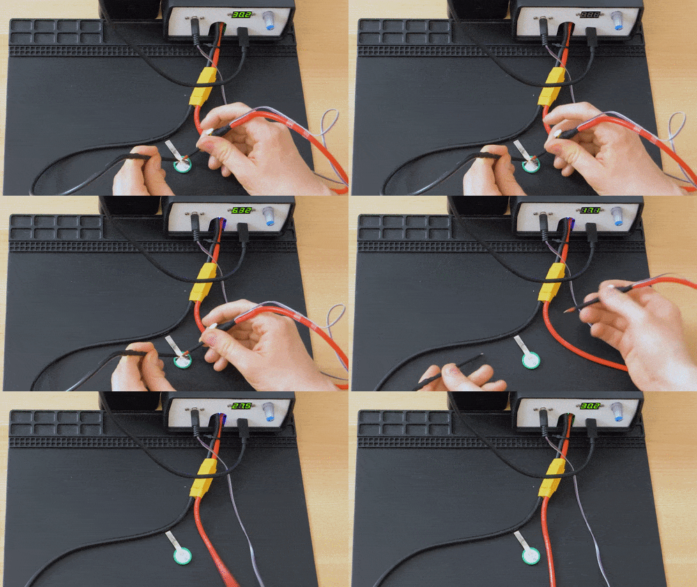
    Spot welding test with a coin cell. Welder is powered off USB-C powerbank.
    You can see how the voltage is instantly reduced to zero and goes up when the spot weld is done.

    This is a close-up look on one of the first spot welds.


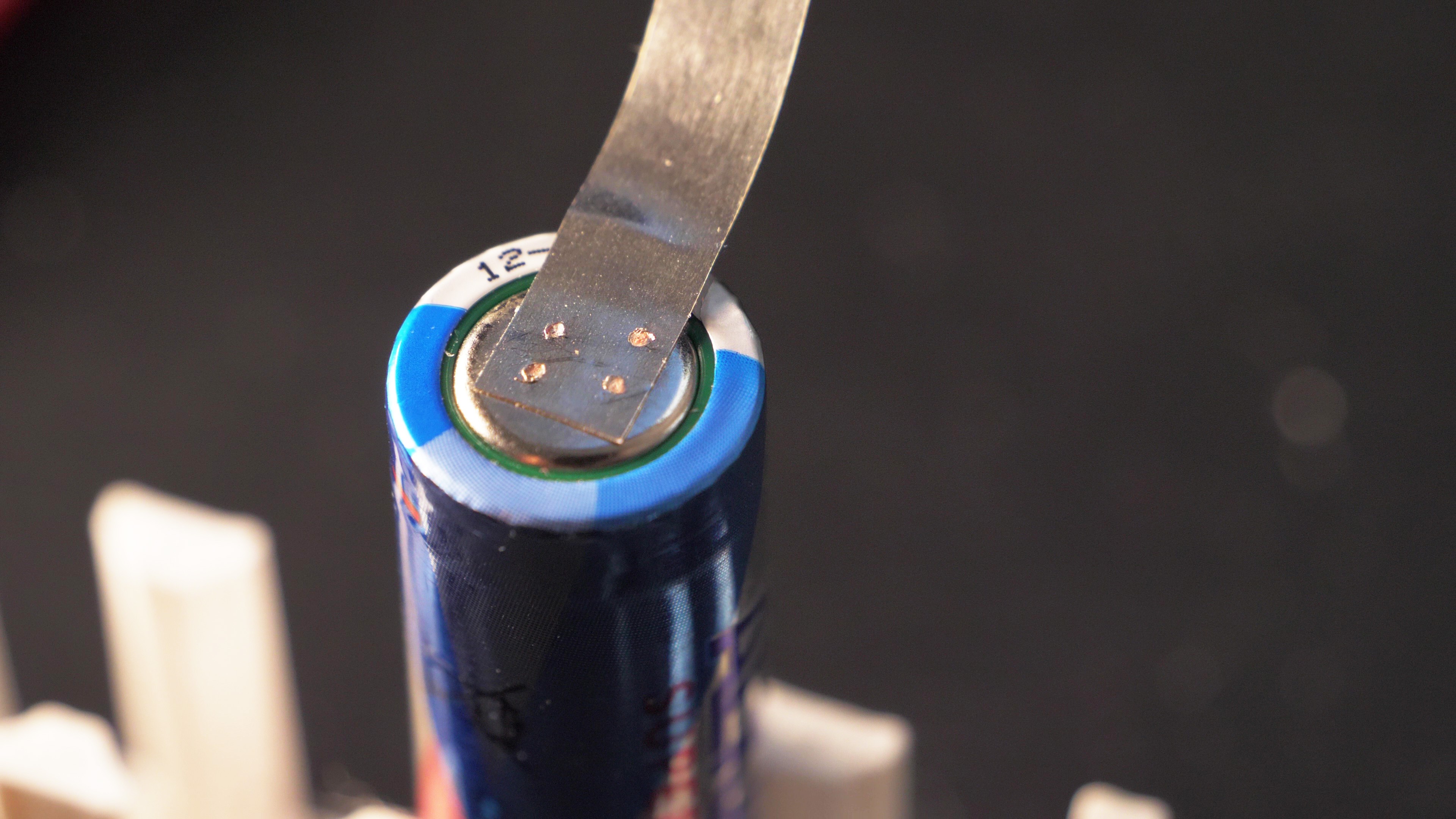
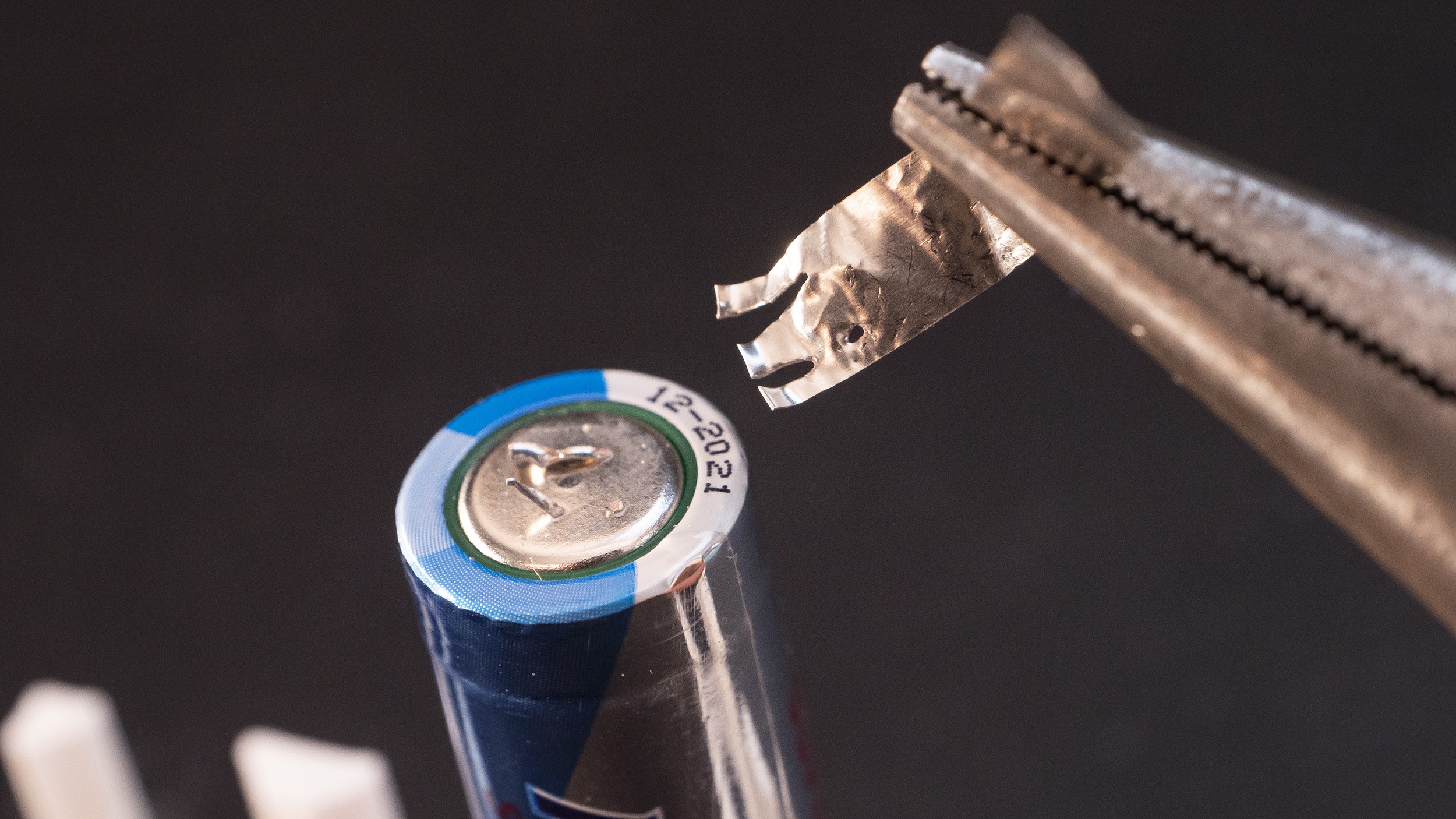
    I was able to hang around 1 kg of weight (1 litre of water) on the metal strip welded to the AA test cell.

    I needed pliers to remove the nickel strip from the cell. You can see that parts of nickel were torn off and there are holes left on the nickel strip, and there are also remaining bits of nickel attached to the cell. This is good, because it means that the welding was pretty strong.

    I only tested small AA and coin cells for now, because that's what I'm mostly going to use with that spot welder (rebuilding Ni-Mh battery packs for older devices), however it would probably work well with Li-ion cells too.

  • Simplified schematic

    Wojciech "adalbert" J10/06/2022 at 00:14 0 comments

    Even though I am mostly using off-the-shelf modules (with some modifications) in this project, maybe it would be also a good idea to have an option to build this spot welder with custom-made, purpose-built PCB. For now I created a simplified schematic which should demonstrate how this device operates. I re-created the relay module using discrete components. However, the step-up converter module is shown as a "black box" for now. I will need to think about a suitable IC which could be used here. Current converter can charge the capacitor bank in around 4 seconds with 12V/3A input, which is a pretty good result. I thought about using MC34063 as a replacement, but it would be at least 4 times slower. And everybody knows it's ancient, but it's also very cheap and easy to be implemented. There are also more modern chips, which are better, but more difficult to implement and more expensive. I will need to evaluate all possible options and decide on something.

  • How it works, choice of components

    Wojciech "adalbert" J10/05/2022 at 22:03 0 comments

    Here is an illustration which shows components that will be necessary to build this spot welder:

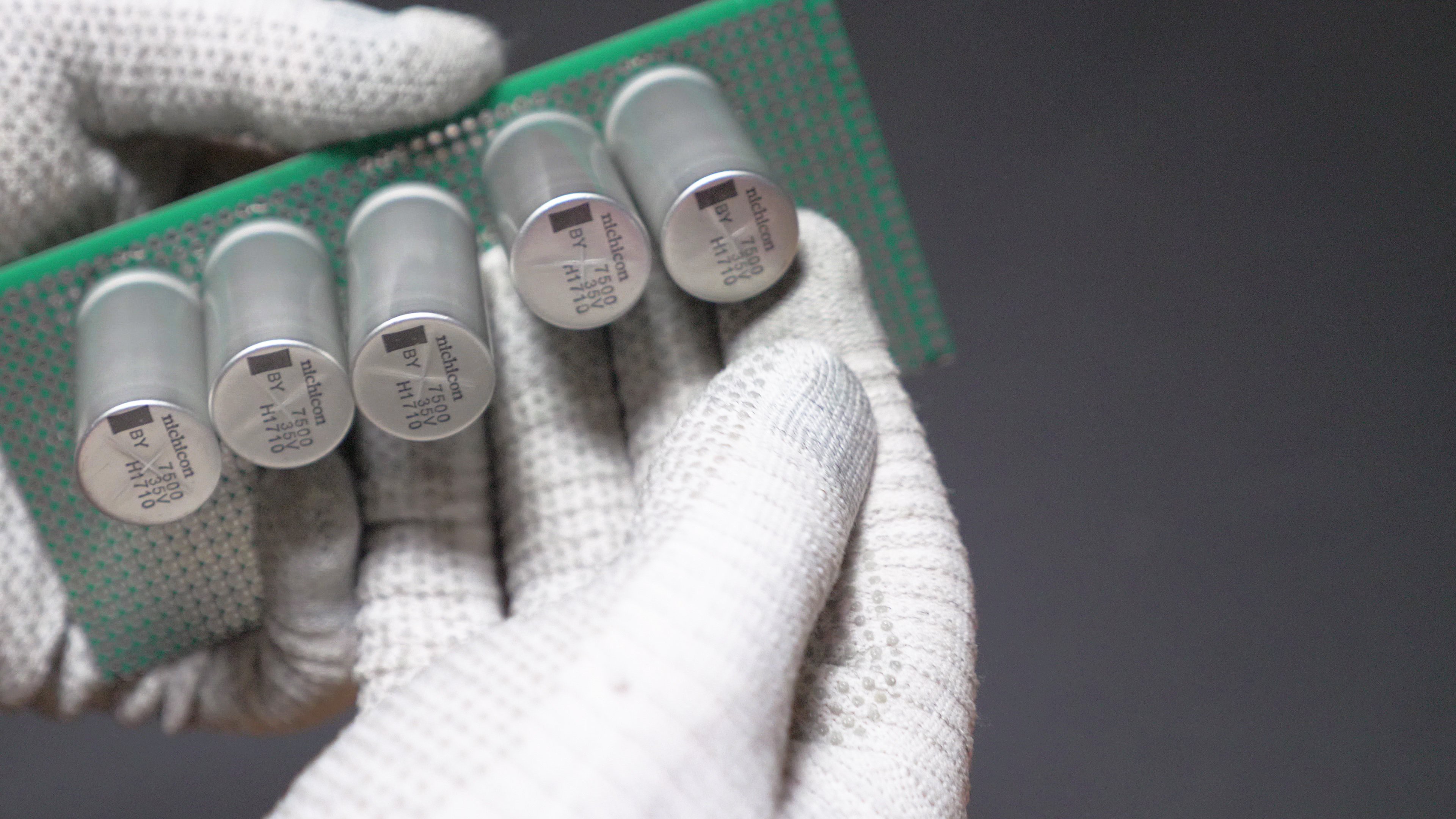
    To make a spot weld, quite a lot of energy will need to be dumped into a small spot in a very short amount of time. To store such amount of energy and to allow quick release of this energy, a bank of capacitors will be used. I used 19 Nichicon UBY 7500uF/35V capacitors connected in parallel, which have total capacity of 142500uF. I will charge them to only 31V at most, because some de-rating of electrolytic capacitors is almost always used, and it should increase the lifespan of these capacitors. 142500uF at 31V will give 64.19J of energy, which should be enough for battery tab spot welding. Each of these capacitors have ESR of 18 milliohms, which drops below 1 milliohm total after parallel connection. That will allow very high welding currents.

    To release this kind of energy, some kind of extremely high current switch will be required. I wanted to use something that will be relatively easy to use, and I chose a second-hand industrial SCR (thyristor) module: T90RIA120. It handles peak currents over a thousand amps and doesn't require sophisticated drivers, unlike MOSFETs. There should be several similar second-hand thyristors which could be used to build such a spot welder. These industrial modules usually have wire terminals, which will allow for an easy installation.

    Before we can weld anything, we need to actually get the energy from somewhere. Capacitors will need to be charged. For the ease of use, I decided to get the power from USB-C input. I used a small 12V USB-C PD trigger module, which will allow use of powerbanks and fast chargers. However, this is not enough yet. This capacitor bank would cause an extremely high inrush current, which would most likely trigger short-circuit protection in the charger/powerbank and the device would turn off immediately. Therefore some kind of current limiter will be needed. It would also be a good idea to step the voltage up, because it will allow for much higher welding energy. Therefore I decided to incorporate a DC-DC step-up converter CC/CV module, which will both increase the voltage and limit the current. I also added an external potentiometer which will allow to change the desired voltage easily. I also added some bleeder resistors to capacitor bank, to allow for quicker voltage changes. I also added a voltmeter module which allows for easy monitoring of the voltage.


    The only thing that remains is a triggering circuit. There is one caveat associated with using a thyristor: once it starts to conduct, it will conduct until the current drops, even if we are no longer triggering the gate. Therefore i will need to use a circuit, which will simultaneously stop charging the capacitors and send a pulse to the gate of the thyristor. I decided to use an off-the-shelf dual 12V relay module for that pulse. However, I made some small modifications. I wanted to add some "cool-down" time after each welding pulse, so I added a simple timing capacitor to the trigger input. I also wanted to make sure that after each trigger button press only one brief pulse will be sent to the gate of the thyristor. To achieve this, I added a second capacitor which is constantly being charged, and once the trigger is pressed, it is discharged through relay contacts into the gate of the thyristor. This is important for safety reasons. The welding should only be triggered when both welding electrodes are touching the workpiece. If welding would be triggered when electrodes were in the air, and only after that they would touch the workpiece, a shower of big sparks would appear. However if we are sending only a single pulse to the gate of the thyristor, we should be safe in case of a user mistake, because the welding will happen only if everything is set up correctly when the trigger is first pressed. I will post details on modifying the relay circuit in follow-up instructions.

View all 7 project logs

  • 1
    Preparing the capacitor bank

    Because we are going to deal with extremely high welding currents, we need to have sturdy connections between capacitors. I am going to use 19 x 7500uF 35V Nichicon UBY capacitors.

    All capacitors need to be connected in parallel. Shape and of the capacitor bank can be different depending on the type of case, or type of capacitors that are used, but in any case all positive leads need to be connected together and all negative leads need to be connected together. Leads of capacitors on the left and right side needed to be bent and twisted a little in order fit in my case.
    The following illustrations shows how the connection is going to be made, and where the charging wires and high current welding wires will be connected later:

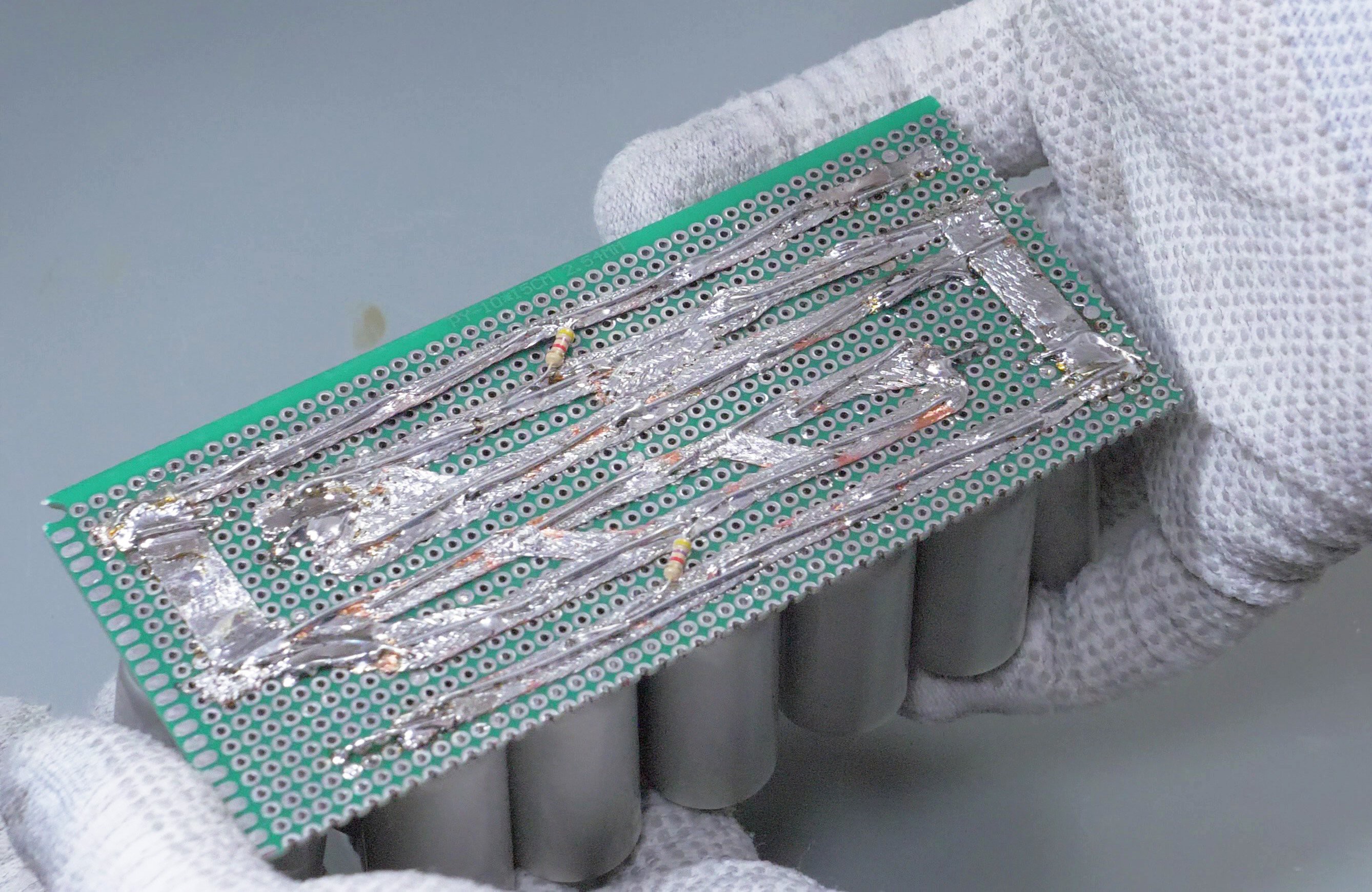
    First I'm going to insert the capacitors to a double-sided perfboard with metallized holes, pre-cut to the appropriate size.

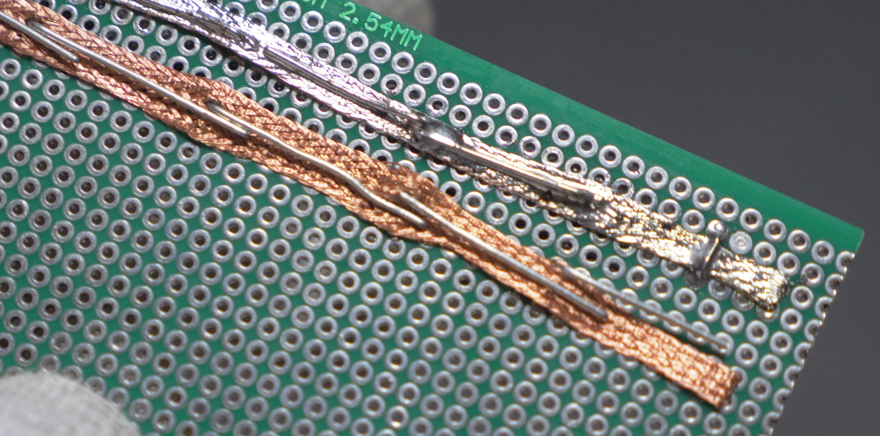
    I am using some pieces of copper wick to enhance the current carrying capacity:

    After the copper wick has been pushed through the legs of capacitors, I bend the legs and apply fair amounts of solder. This process needs to be repeated for all rows of capacitors. Please mind the polarity! The capacitors need to be connected in parallel.

    This is how a soldered capacitor bank should look like. It might look a bit different depending on the amount and size of the capacitors. I also added high-value bleeder resistors which will force the capacitors to discharge over time (which is good for safety and also allows quicker voltage adjustments if the voltage is stepped down). Note the thicker copper areas on left and right sides: cables will be attached here in next steps.

  • 2
    Modifying the relay module

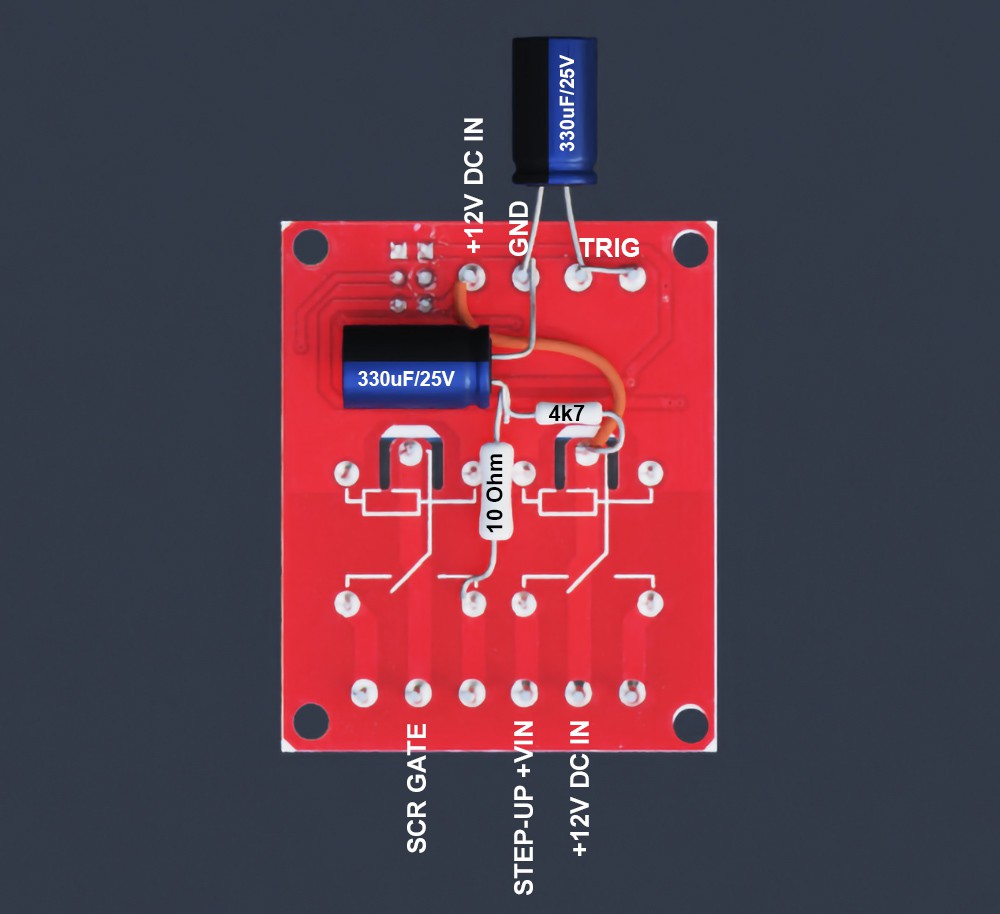
    This is how the bottom of the HW-279 relay board should look after the modification. You need to make these modifications if you want to make this spot welder using off-the-shelf modules. If you want to make a custom PCB instead, you can skip this step and proceed with building a custom PCB.

    Four components are added: two capacitors and two resistors.

    First capacitor is added between GND and TRIG pins (TRIG turns the relays on). It will cause the relays to turn off with a delay (around one second). This is needed to make sure that the capacitor bank has been completely drained before charging will start again. This capacitor doesn't need to be soldered, it can be pushed into screw terminals.

    Second capacitor is soldered between GND and a junction between two resistors. This capacitor will store the charge which will be used to trigger the gate of the SCR. When the relay is turned on, this capacitor will be discharged into the gate.

    First resistor is 4.7 kOhms, which is used to "trickle charge" the capacitor responsible for firing the SCR gate. The resistance is high enough not to trigger the SCR gate by this resistor itself (but a fully charged capacitor will trigger the SCR).

    Second resistor is 10 Ohms, 1W. It adds some resistance between SCR gate and capacitor, to minimize the chance of sparks and sticking of the relay contacts.

  • 3
    Preparing the wires and cable connectors

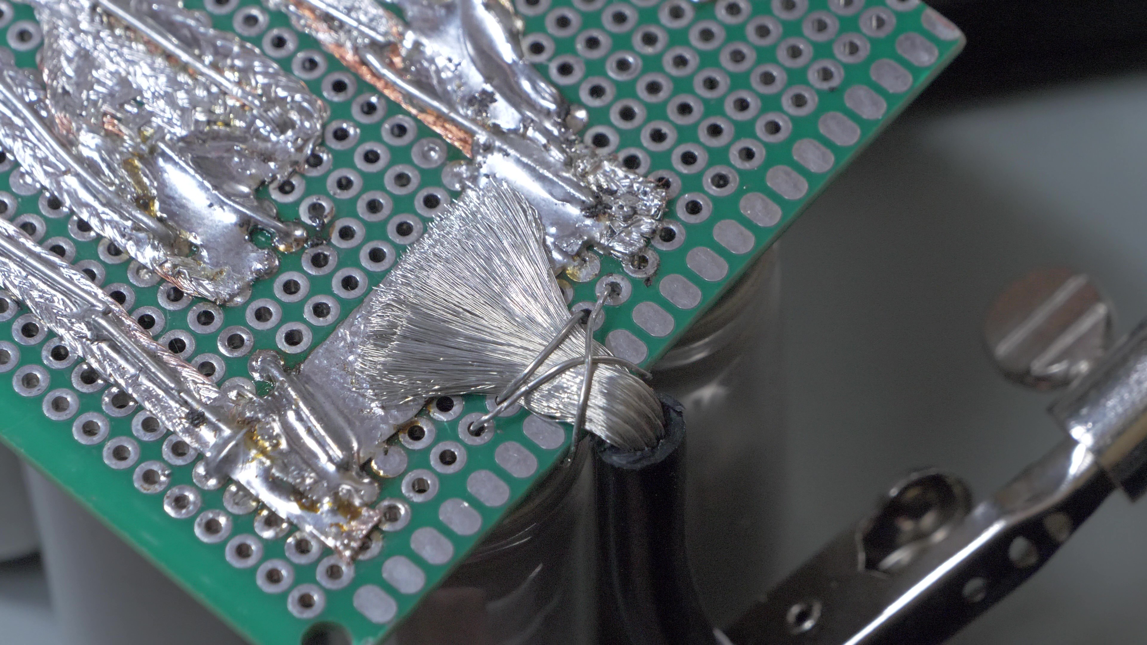
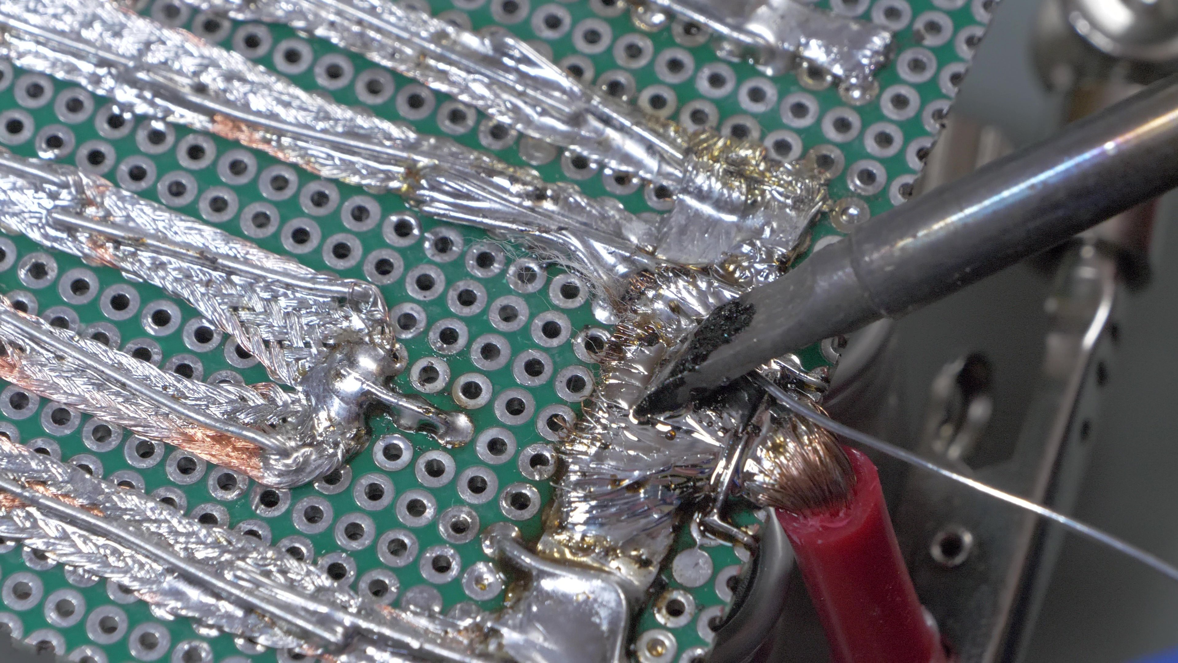
    Now 10 AWG silicone wires need to be attached to the positive and negative tabs capacitor bank. Before soldering, I wrapped the stripped ends with some additional pieces of wire to make them stay in place. Then I applied some solder to the wires.

    After soldering, the burnt flux can be cleaned with isopropyl alcohol.

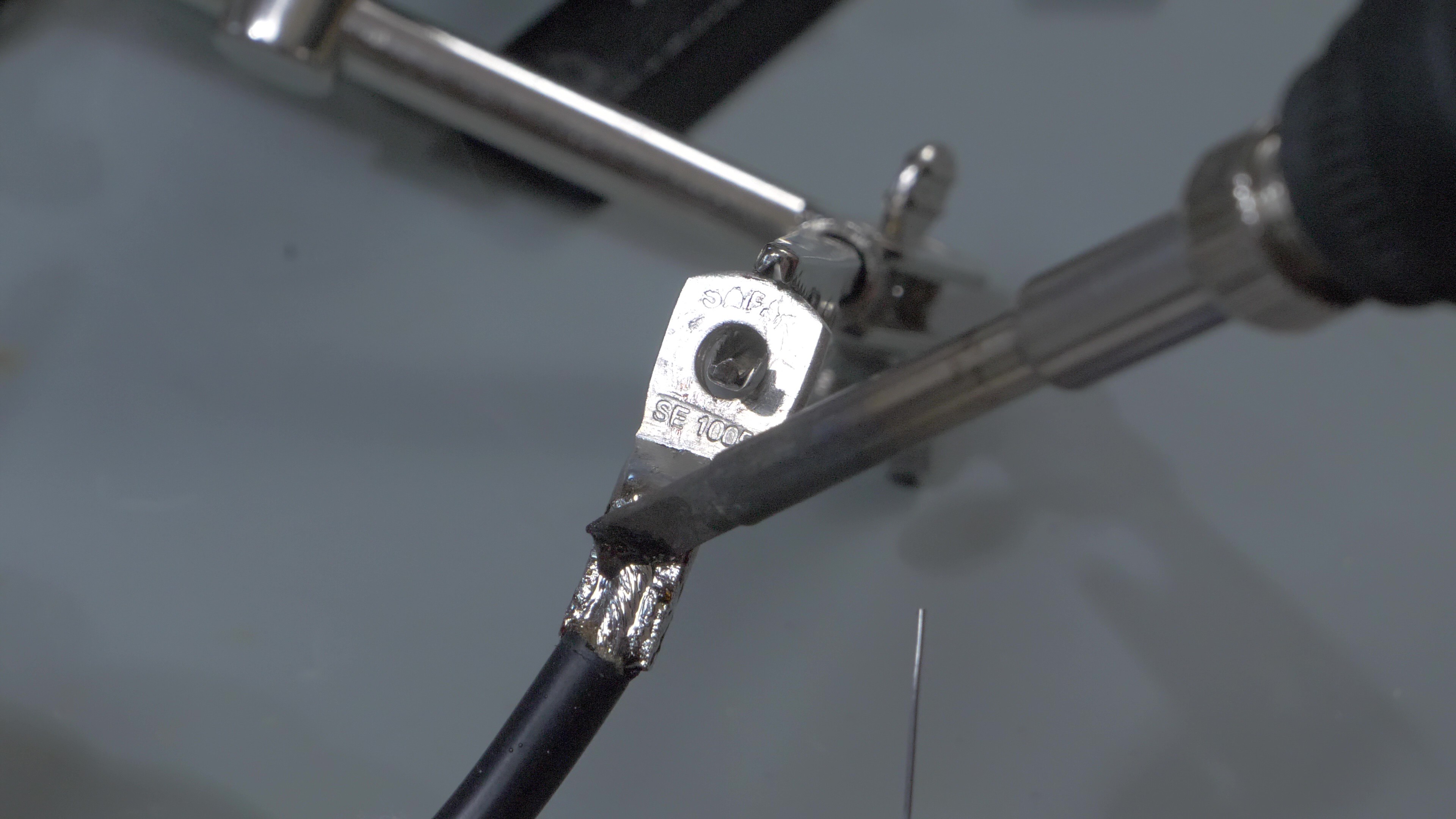
    Now the negative wire needs to be terminated with a cable lug (5mm diameter hole). I didn't have a proper press, so I cut out the top of the cable lug and soldered the wire, instead of crimping it. Remember to insert a piece of heatshrink before soldering.


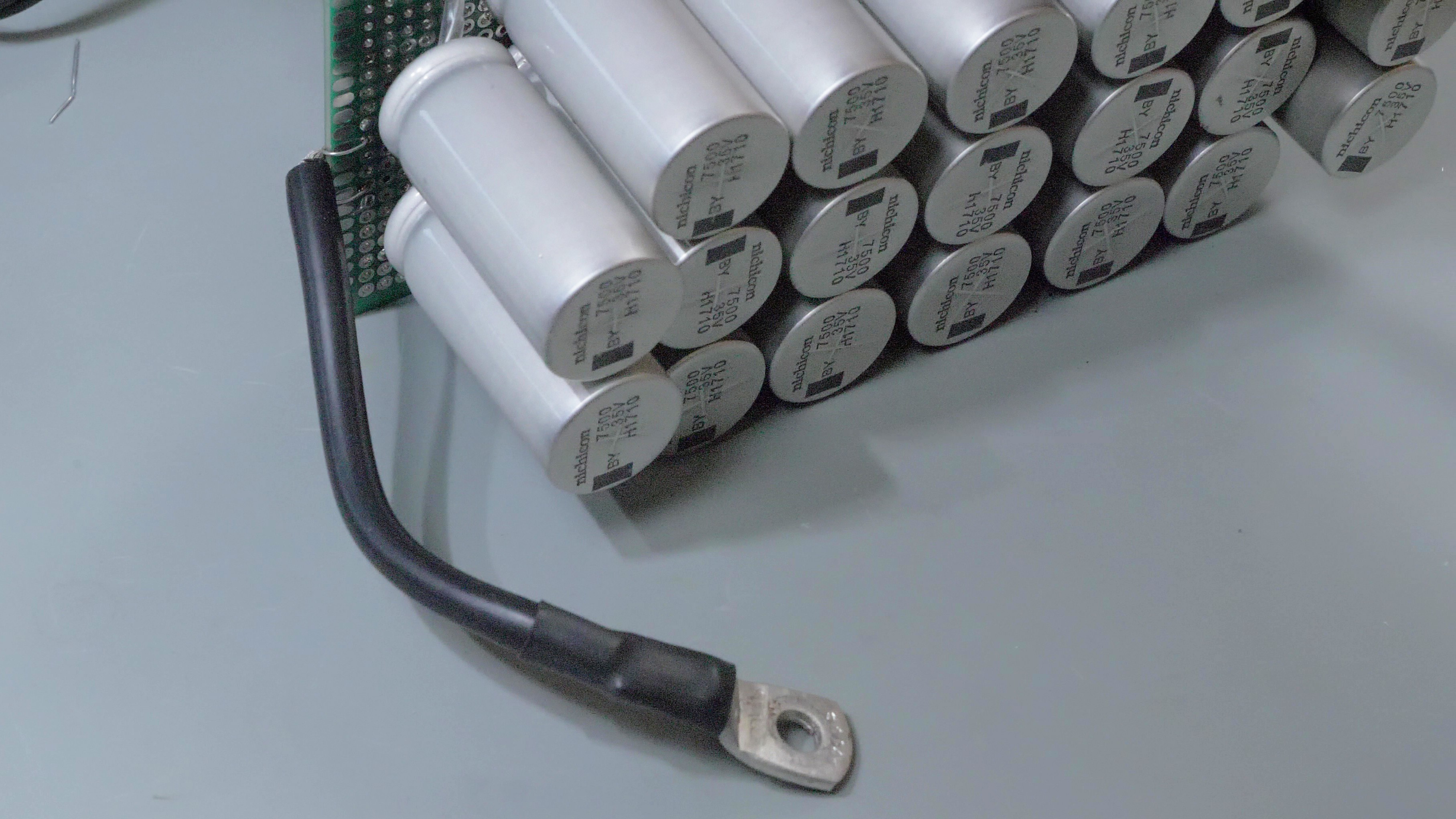
    This is how the negative cable should look like after soldering and applying the heatshrink. 

    Another short cable (negative/black) needs to be prepared, with one side terminated with a wire lug. The positive (red) cable remains unterminated for now.

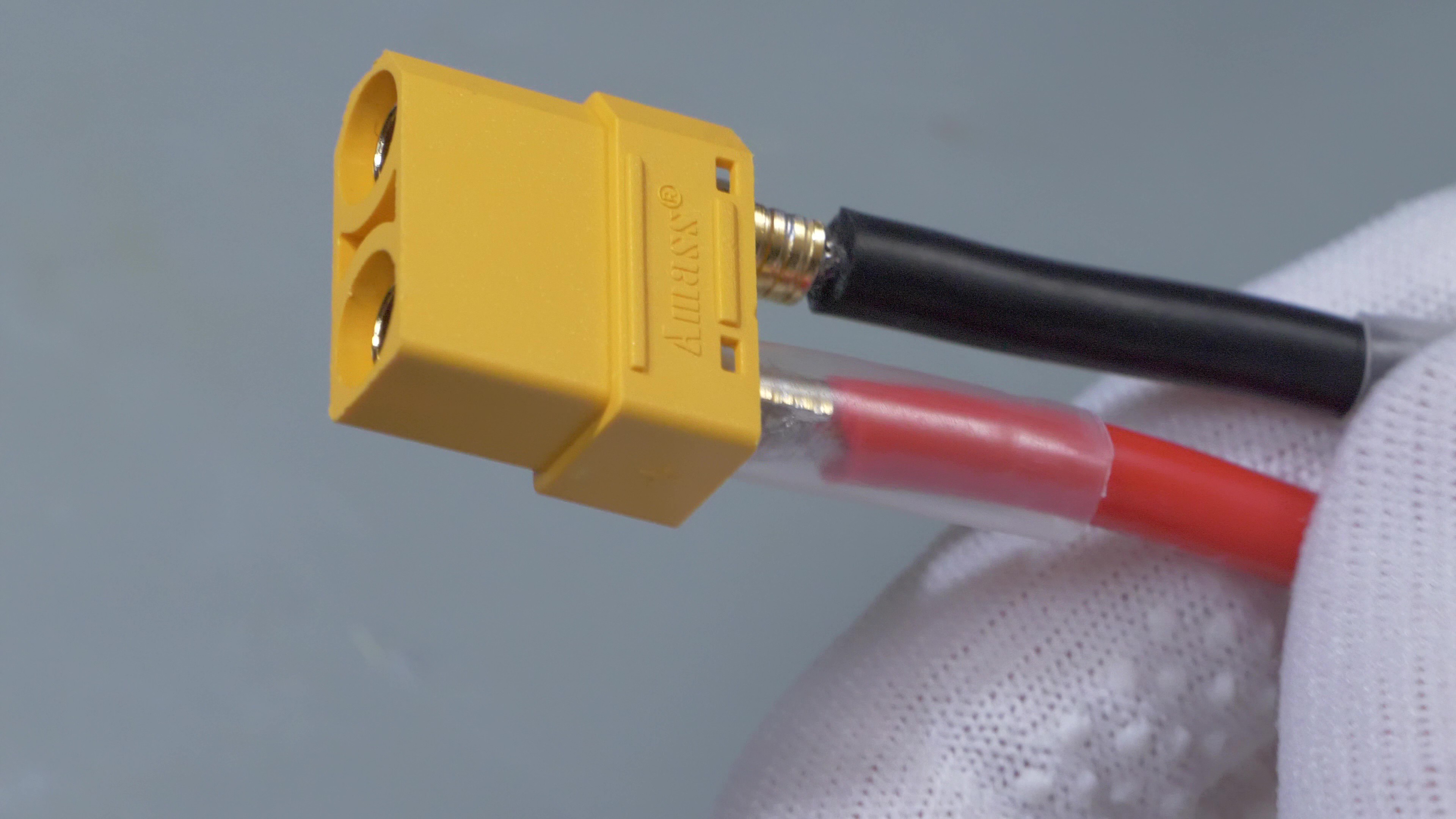
    Now an XT90 connector needs to be soldered to the stripped ends of positive and negative cables. This is where the welding probes will be connected later.

View all 6 instructions

Enjoy this project?

Share

Discussions

Lynneandpeter4947 wrote 03/26/2024 at 03:53 point

Using a 370000uF capacitor bank (37 cheap, unbranded Chinese 35V 10000uF aluminium electrolytic capacitors 18*35mm, low ESR) and the same 12v dual relay, DC to DC converter, timing capacitor and RC pulse control described in Adalbert's original project I am successfully spot welding .3mm pure nickel strips (with the capacitor bank charged to 30.7v), .2mm pure nickel strips (with the capacitor bank charged to 21v), and welding .15mm pure nickel strips with the capacitor bank charged to 15.8v; but the up-to 7kA pulse produced by the larger capacitor bank did cause the T90RIA120 thyristor to fail (probably because the max ITSM of the 90A thyristor was exceeded by ~ ×2, even though the pulse would have been ~1ms compared to the 10ms limit in the 90A thyristor specifications). The damage to the 90A thyristor caused it to be permanently switched on.

I replaced the damaged T90RIA120 thyristor with a stud thyristor (Semikron SKT300 series with an ITSM of ~11kA). It is bulky and therefore external to the 160 x 110 x 90mm plastic case into which I had squeezed the 37 x 10000uF capacitors, the original T90RIA120 thyristor and the other components, but it is effective. The stud thyristor is inserted inline with the negative probe cable, and the cathode cable is bolted to the same connector inside the case as the original T90RIA120 thyristor. The thyristor gate is triggered by the same 12v RC circuit described in the original project.  The stud thyristor has further lowered the voltage required to spot weld (see my stats for welding .15mm nickel strips using the original 90A thyristor and 370000uF capacitance in my earlier comment). I suspect the discharge time using this larger thyristor has been reduced to <1ms (probably .00055ms), assuming the amperage needed to spot weld specific nickel strip thicknesses using Adalbert's design is much the same regardless of the size of the capacitor bank and capacitor bank voltage. I don't have an oscilloscope to confirm my theory.

To protect the DC to DC step up converter from unintended discharge from the capacitor bank I inserted a 40v 3A diode between the capacitor bank and the converter, notwithstanding the converter  specifications include output reverse voltage protection, and the diode causes minor forward-direction voltage drop.

In conclusion, as Adalbert contemplated, I confirm it is feasible to use cheaper capacitors; and increasing capacitance by 250% enables spot welding of .3mm pure nickel strips at 30.7 volts, and thinner strips with significantly reduced voltage; however, increased capacitance has led to deviation from Adalbert's original imperatives of compactness and low cost; the heavy duty stud thyristor cost twice as much as the T90RIA120.

  Are you sure? yes | no

Lynneandpeter4947 wrote 02/28/2024 at 04:10 point

Final result using a 370000uF capacitor bank (still with max 31v input):

.1mm nickel strips 21v 5.6kA

.15 nickel strips 24.5v 6.3kA.

Excellent welds; no sparks or tip fusion etc. (3mm diameter copper probes have 1mm conical points and I apply moderate pressure).

There is no indication the 90A thyristor can't handle the high pulse current, although its use has been limited so far. I will post a final comment once I have tried welding .2mm nickel strips. (Extrapolation suggests .2mm will require 29v with a pulse of 7.4kA.) 

  Are you sure? yes | no

Lynneandpeter4947 wrote 02/17/2024 at 02:14 point

I'm stll waiting for another 20 x 10000uF capacitors (and have 6 redundant 10000uF capacitors soldered in place awaiting to be paired when the final order arrives) but have connected the circuit in the interim to test components. With only 14 x 10000uF capacitors in the circuit (close to the capacity of the 142500uF capacitor bank in the original project) I am able to weld strong joints with .1mm pure nickel strips at 26V, and .15mm pure nickel strips at 28.5V (3kA). I have 14 square mm of cable to each probe ((doubled up AWG10 (3mm dia.) silicon copper cable)), so resistance is negligible. Probes are 3mm dia. copper wire with 1mm dia. tips.

I'm still concerned the 90A thyristor will not cope with >4.7kA pulses (even for 1mS) with sustained use. If 200000uF will weld .2mm strips using <31V I'll probably just use a 200000uF bank, which (only!) generates 4.1kA.

My 12v power supply is an 18v Makita battery pack with a buck converter I had. I tried an L7912 to regulate power but didn't have the correct capacitors to control the input and output, but will try again later.

  Are you sure? yes | no

Lynneandpeter4947 wrote 01/28/2024 at 04:59 point

I had assumed the key criteria for welding increased thickness of nickel strips was current. The original project estimated ~3kA using 14.2mF, and he said he could easily weld .1mm nickel strips (I presumed he meant pure nickel). 20mF should produce ~4.1kA. I was concerned about whether the 90A SRC thyristor could handle repeated surges of 4kA, even for 1ms with a couple of seconds delay between each weld.

I take your point about trying the penetration capability using any 12v power supply before introducing the 18v and L7912. I'll let you know how it goes in a few weeks (I'm on vacation).

  Are you sure? yes | no

jandy123 wrote 02/01/2024 at 19:14 point

Thyristor is 50RIA120 bought here https://www.amazon.nl/-/en/Thyristor-50RIA120-Rectifier-Convectors-Controlled/dp/B08CDF573F. So far so good ;).

And the cap bank is 100mF, using this https://www.amazon.de/-/en/dp/B09JB94CDX?psc=1&ref=ppx_yo2ov_dt_b_product_details to be clear.

Good luck with your build and please share here your outcome! 

  Are you sure? yes | no

Lynneandpeter4947 wrote 01/23/2024 at 07:38 point

I am using an 18v power source (Makita battery) and therefore putting an L7912 regulator on the negative line to drop voltage to a continuous 12v. The 10 uF cap is inserted after the voltage regulator to filter out any noise or high-frequency (ac) signals that may be on the DC line. This may be unnecessary because the circuit probably isn't that sensitive. I also think that having an L7912 should do away with the need for a fuse for the 12v supply, but I'm not sure about that.

  Are you sure? yes | no

Lynneandpeter4947 wrote 01/21/2024 at 11:22 point

Hi jandy123,

Has your 50mF set up performed as expected? Any problems with the amps (50A) of the thyristor, and has it held up to sustained use? 

I intend using a bank of 20mF/35v (20 x 1mF) without making any other changes to the posted project; I want to achieve at least .15mm welds on pure nickel strips.

  Are you sure? yes | no

jandy123 wrote 01/22/2024 at 16:43 point

In the end I used a 100mF cap. bank and followed the images for setting  the relay delays.  See my comments below. So far so good, I can solder 0.1mm nickel strips just fine, between 28 and 30V. Lower than 28V, I do not achieve proper bound. I would strongly recommend, allowing the possibility of larger than 30V (this imposes caps requirements and boost converter).  Unfortunately I cannot try >30V, and I also do not have 0.15mm strips.

  Are you sure? yes | no

jandy123 wrote 01/24/2024 at 22:00 point

20mF will not be enough  to weld 0.15mm strips. You will probably need at least 150mF @35V.

  Are you sure? yes | no

Lynneandpeter4947 wrote 01/21/2024 at 03:12 point

I am in the process of replicating your project.

The image of the bottom of the HW-279 relay board shows a 330uF/25v between Gnd and TRIG; but the circuit diagram shows a 100uF/35v. Did you make this imcrease to a 330uF/25v to tweak the timing delay?

I am adding a single LM7912 to regulate voltage from 18v to 12v, provided the 12v circuit is <1.5 amp. I plan to include a 10uF output capacitor. Are you able to confirm a single LM7912 will suffice?

  Are you sure? yes | no

jandy123 wrote 01/22/2024 at 16:45 point

Yeah, I faced this too. In the end I used two 330uF caps on both triggers.I Btw.,  I "limit" current with two series 12V halogen bulbs allowing for 2amps in series with a cheap non-isolated, non-CC boost converter. I power everything with a beefy xbox360 (at 12V capable of 10amps).  

What do you mean with 10uF output cap???

  Are you sure? yes | no

jandy123 wrote 01/24/2024 at 22:04 point

For the boost convertor (12V to about 30V) the 1.5amp may not be nearly enough, unless you use a current limiting boost converter and a very small cap. charge current. That will result I think in large delays between successive welds.

I would first get the circuit running from 12V (without the LM7912), make sure the cap. bank is large enough for 0.15mm strips and then worry about powering the circuit from 18V.

  Are you sure? yes | no

jandy123 wrote 12/12/2023 at 17:52 point

Very nice project, quite smart actually, compared to the many fakes around "capacitor spot welder". 

I'm trying to build my own, using for now a 50mF capacitor bank. (No clue if this is large enough, but time will tell.) For now, I have the cap bank powered by a 18V/1A trafo, with which I can blow out strips, scissors, etc., but no proper binding/welding on batteries; using even 0.1mm strips.  However, as far as I understand, either i) energy is not enough (easy to solve -- add more caps???), or time of contact/discharge/melting is not appropriate. So, I thought to address  the latter,  I should give this  nice project a shot. After looking at the info, I see that the schematics changed compared to the detailed info regarding the relay mod.  Could you please let me know which I should follow? Some more/up-to-date info from your own findings, about settings, energy needs, etc. would be greatly appreciated! 

Anyhow, great, simple and smart solution!

Thanks in advance!  

  Are you sure? yes | no

jandy123 wrote 12/20/2023 at 19:13 point

Answering to my self (in case it helps anyone). I did it using the relay mod schematics, for the rest following the "main" schematics.  I used a cap bank of 100mF made of 10x10mF 35V cheap low-esr caps, a cheap non-CC boost module (used two halogen light bulbs in series to limit  the current somewhat) and a cheap 50RIA120 thyristor clone. It works quite well, in the sense that I'm able to spot weld 0.2mm strips at about 28V.

*** Correction 0.1mm strips ***

Definitely better than my 4V battery powered device (which run out of battery) and than most youtube "capacitor spot welder" fakes.

  Are you sure? yes | no

David Forrest wrote 11/10/2022 at 18:10 point

Your schematic says "Low ESR Capacitor bank (~1mΩ total)" but the Nichicon UBY 7500uF/35V caps are like 20mΩ  How does that work?

  Are you sure? yes | no

Wojciech "adalbert" J wrote 11/10/2022 at 18:59 point

Capacitors are 18mΩ each and there are 19 of them, and because they are connected in parallel, I just assumed that total ESR equals 18mΩ divided by 19 = 0,947mΩ

  Are you sure? yes | no

David Forrest wrote 11/10/2022 at 20:42 point

Ah. So if I had 3x 47000uF caps with 18mΩ handy and used  them instead of the 19x 7500uF, I'd have about the same capacitance but 6x the ESR.  With the Thyristor's 2.5mΩ and 2 foot of 10 gauge being about 2mΩ, it would be about 10.5mΩ vs 5.5mΩ.  If the weld material isn't a significant resistance, then maybe the higher ESR capacitor bank might have half the peak current for the same charge.

  Are you sure? yes | no

Matthijs Kooijman wrote 10/13/2022 at 06:14 point

I got a lipo-powered spot welder from ali last year. It was reasonably nice, produced not-so-bad welds, but I was a bit worried about having a *big* lipo in there. However, it turned out the control circuitry was badly designed, so the lipo was completely flat after it was on the shelf for a couple of months...

However, your design sparks an idea: Use your capacitor bank as a power source for the welder I have (so I can still use its pulse timing, connectors, etc.). Will have to properly check allowable voltages and currents, though...

Thanks for sharing this!

  Are you sure? yes | no

jandy123 wrote 12/12/2023 at 17:55 point

I'm in the same boat! Have you ever managed to recycle the thing, apart from replacing battery?

  Are you sure? yes | no

farrell.segall wrote 10/12/2022 at 18:51 point

Great idea. 

I was considering doing this with a bank of supercaps from a discarded project each 3Farad but at 3V - just not sure if that would work though.

  Are you sure? yes | no

Wojciech "adalbert" J wrote 10/12/2022 at 19:20 point

Thanks! Not sure if 3V wouldn't be too low for a thyristor, as it has some noticeable voltage drop. And charging low voltage supercaps would be slower.

It should also be kept in mind that in my design all of the energy from capacitors is dumped into the nickel strip instantly, at once. Oversized bank of supercapacitors could store so much energy, that it might melt the nickel strip completely. Some kind of pulse time control would be needed, which is not possible with a thyristor (a thyristor will stop conducting only after the capacitors are discharged completely, or the circuit breaks in another way). Maybe it would work if you used only 4 or 5 supercaps in parallel, so they won't be too powerful, but now the question is would they be able to put enough amps into the welding pulse.

Of course It certainly is possible to use supercapacitors in a spot welder, as I saw some existing designs, but they usually have precise pulse control with MOSFETs and microcontrollers, and these supercaps are treated in similar way as batteries. Regular electrolytic capacitors are easier to use without sophisticated pulse control system.

  Are you sure? yes | no

farrell.segall wrote 10/12/2022 at 20:13 point

Yes all noted. I recently worked on reparing a large plasma torch and replaced some very high current MOSFETs which I now have some spares. Also regularly use a two transistor 'spike' generator which could work. Always fiddling around witn stuff here but have access to a huge bag of these supercaps so worth a try.

Thanks for the feedback.

  Are you sure? yes | no

Jason Alexadner wrote 10/12/2022 at 16:54 point

I recently put together a k-weld. There wasn’t much else out there, other than some sketchy Amazon products. Your design is a better starting point, I think, for someone who needs a few spot welds now and then.

  Are you sure? yes | no

Wojciech "adalbert" J wrote 10/12/2022 at 19:26 point

Thanks for the comment! This design doesn't have any batteries, so even if you use it once in a year, there shouldn't be anything that will degrade over time (i hope the caps will last for years and hopefully decades), and there are no self-discharge issues to worry about.

  Are you sure? yes | no

Similar Projects

Does this project spark your interest?

Become a member to follow this project and never miss any updates