 Lithium ION
Lora based switch projects are simple and very useful for long range application. Specially in the agriculture and industrial field. As the name specify LoRa “long range radio” gives a pretty good RF signal range up to 15km with high gain antenna. In this tutorial we will make Lora based transmitter and receiver to turn ON/OFF two channel output. With a connection LED to know that both the modules are paired. In this way we can monitor the connectivity range as well as real time operation of the LoRa.

LoRa comes with two type of connection interface, SPI and the UART. But here we are using SPI LoRa because it works on 3.3volt logic and Arduino works on 5V logic level. In UART we need an external logic convertor to establish the connection. Also, a software serial is required to get the output of serial monitor on another channel. And due to limited libraries UART based Lora is not available to me in 433Mhz range.
LoRa SPI:
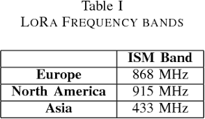
Serial peripheral interface uses MOSI, MISO and SCK pin of the microcontroller. But in LoRa there is a chip select, Reset and Digital pin to be connected. Which extend the wire connection to 8 pins. No need to use any external logic convertor with this type of connection setup. Here in INDIA 433Mhz spectrum is given to LoRa, you can check your country bands accordingly and then update the code.
Win exciting rewards from PCBWAY:
PCBWAY is hosting a PCB design competition 5th time and now there are rewards for everybody. Just register on the website and get your hands on raspberry pi Pico board.

You can share your projects and thoughts there to win more prices. Just upload the full working of your best project using PCBWAY service. Want to know more about contest then click here.
Components required:
1) LoRa Ra01
2) Arduino UNO
3) Battery
4) Tactile Switch
5) LED and 220ohms resistor
6) PCB shield from PCBWAY
Circuit diagram:
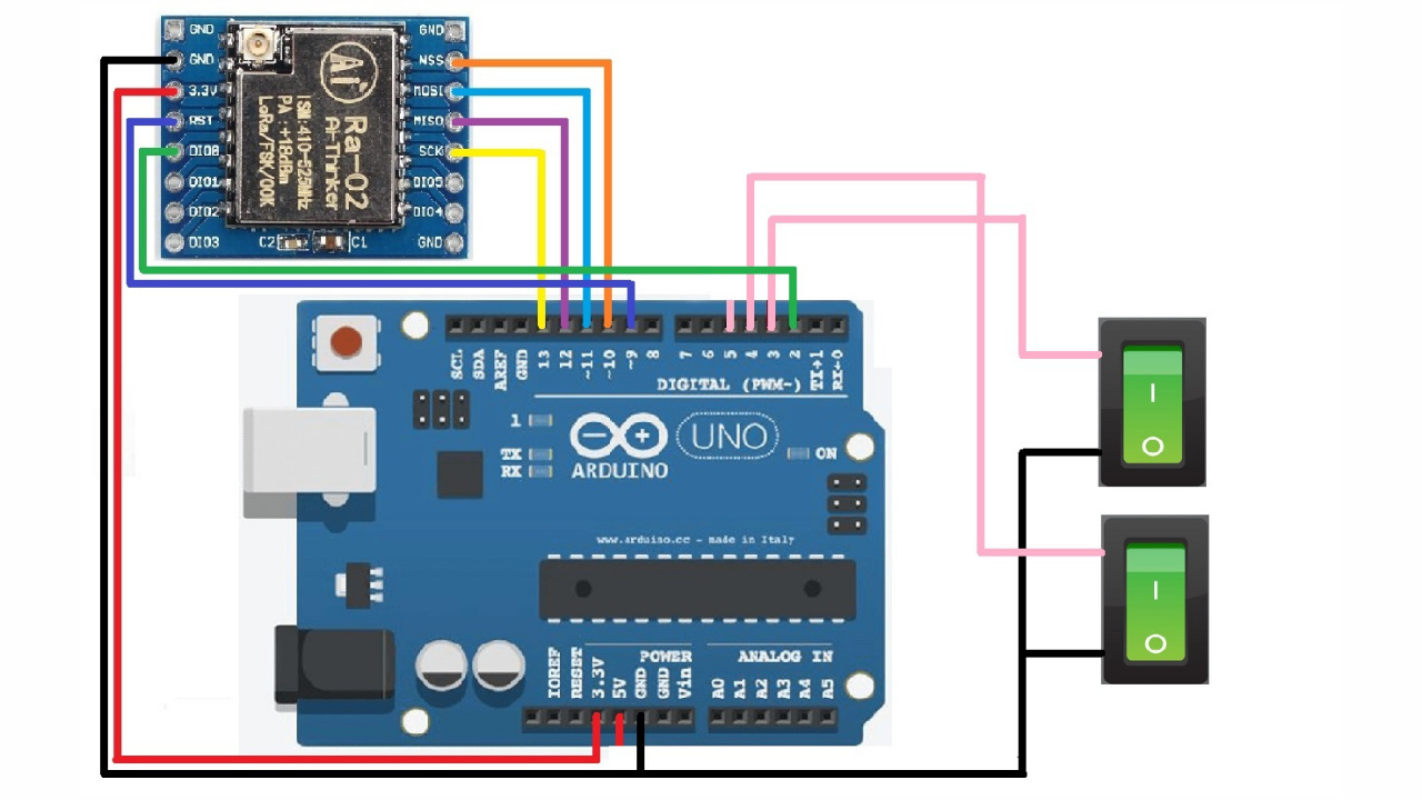
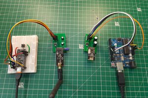
The circuit diagram is same for the Lora connection. MOSI to D11, MISO to D12, SCK to D13, D10 for NSS and D9 for the Reset. but there are modifications done on switching side. In the transmitter section two tactile buttons are connected to D3 and D4 pin of the Arduino. Buttons are work in hold state only. The output at receiver end goes ON/OFF by pressing/releasing tactile button respectively.

On the receiver end we are using a string receiver LED on pin D3, which gives the information about connection. This LED will blink after every second and gives the information about the successful connection of LoRa RF signal. We are using D4 and D5 as the output, by default these pins are hold high and go to low as the button pressed from the transmitter. This type of code is done for the Relay based application of the LoRa.
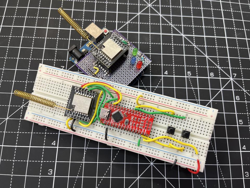
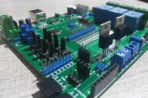
PCB shield and prototype:

I made a prototype for the transmitter but a dedicated PCB is recommended for it. I am using Pcbway service- China based PCB manufacturer. These hole type pref board I got from PCBWAY but you can download the dedicated PCB shield files from here.

There are a lot of connections in the PCB that why shield is recommended to use. Get the PCB in just $5 for 5 pcs of 2layer board. Register now to PCBWAY and get free rewards as coupons. There is some limitation in holed type design because they are made to try different projects. And soldering wires properly through them is not an easy job. Get a full soldering guide soon here.
Code and Libraries:
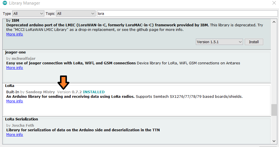
Here I am using LoRa library by Sandeep Mistry, it is very well optimized library for SPI protocol LoRa modules. You can also see more examples and go through each of them in order to make some new projects.
For Transmitter:
#include <LoRa.h>
//int pot = A0;
const int SW1 = 3;
const int SW2 = 4;


int SyncWord = 0x22;

void setup() {
  Serial.begin(9600);
  pinMode(SW1,INPUT_PULLUP);
  pinMode(SW2,INPUT_PULLUP);

  cli();                                    //stop interrupts
                                            //set timer1 interrupt at 1Hz = 1sec
  TCCR1A = 0;                               // set entire TCCR1A register to 0
  TCCR1B = 0;                               // same for TCCR1B...
Read more »

 ElectroBoy
 ElectronicABC
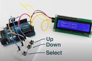
well? whats the range achieved? U said LoRa!