 ElectronicABC
PCB gerber:
https://mega.nz/file/LVAxHJAb#uA_gfaO8A09VXXjK_Opzy3N1udc21OqgJpwgq9CUmSI
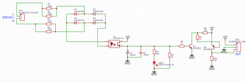
SCHEMATIC DIAGRAM
Here we can see the schematic diagram of the project.
FUNCTIONING
This circuit is very easy to make and interpret: we have 4 100k resistors at the input that will reduce the input voltage for the optocoupler's LED, in turn we see the diode bridge that converted the alternating current to the pulsating current and when connecting at the alternating voltage input, the optocoupler LED will be activated and also the optocoupler transistor and will activate the TTL output control stage, that is, the LED of the control stage will be activated and let the 5V pass and thus I will have an output pure 5V to activate some microcontroller or take it to binary logic.
In this way we can control any electronic device and we can use it in an automatic transfer system where we can visualize or take a census of the current of the network and the backup current and be able to supply the different loads within a house and we will obtain the quick response if the power grid goes.
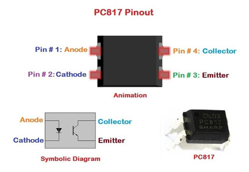
PC817
The PC817 is a general purpose optocoupler consisting of a diode that emits infrared light towards a phototransistor, driving the transistor optically, it has a single channel DIP-4 package.
What is the PC817 Optocoupler used for?
It is used to make an isolation between two stages of a circuit, it can be applied in peripherals for embedded systems, AC motor control, control systems and more. The most common applications for the PC817 Optocoupler are:
1. I/O Isolation for MCUs (Microcontroller Units)
2. Noise suppression in switching circuits
3. Transmission of signals between circuits of different potentials and impedances.
SPECIFICATIONS AND FEATURES
• Type: Optocoupler
• Series: PC817
• Package: PDIP-4
• Output type: PhotoTriac
• Number of channels: 1 channel
• If – Direct current: 50 mA
• Maximum forward current IFM: 1A
• Reverse voltage VR: 6V
• Power dissipation P: 70mW
• Collector-emitter voltage VCEO: 80V
• VECO emitter-collector voltage: 6V
• IC collector current: 50mA
• Pc collector power dissipation: 150 mW
• Total power dissipation Ptot: 200 mW
• Working temperature: – 30 C to + 100 C
ELECTRONIC COMPONENTS
• 4 RESISTORS 100K 1/2W
• 4 DIODES 1N4007
• 1 PC817 OPTOCOUPLER
• 3 RESISTORS 1K 1/2W
• 2 RESISTORS 10K 1/2W
• 1 RESISTOR 220 ohm 1/2w
• 1 transistor 2n2222a
• 1 bc558 transistor
• 1 electrolyte capacitor 220uf25v
• 1 capacitor 104
• 1 led diode 5mm
• 1 terminal block 3 pins
• 1 terminal block 2 pins
• 1PCB
FEATURES
• Voltage to Sense 110VAC/220VAC
• TTL output voltage 5V
• FAST SENSITIVITY
• Output control voltage 5VDC-12VDC
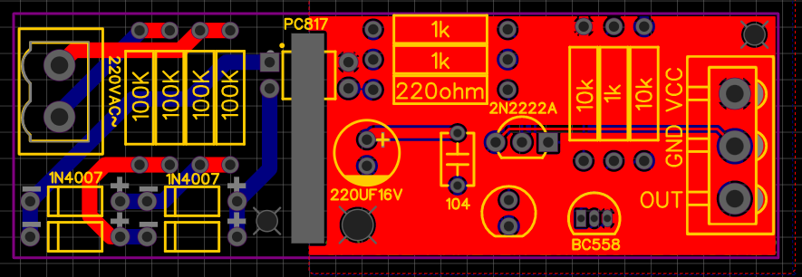
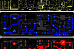
EasyEda
Here we will see the PCB design both the tracks and the 3D image

JLCPCB
Once the pcb is designed,...
Read more »
 Kuba Sunderland-Ober
 w_k_fay
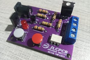
 hesam.moshiri