 ElectroBoy
I am fond of designing different amplifier using different IC and specs. But always there is something new the amplifier. You can see my previous work on amplifier on my profile. Today I have an old 4440 amplifier which is integrated with bass boosted amplifier. this is very old amplifier IC which is very popular in mid-90’s and most of the car stereo systems are designed using this. LA4440 originally made by SANYO Tokyo company and has a max 19w output. Which is decreased to 6w per channel if used in stereo channel. I don’t know about the decrease in output but the info is given in the datasheet itself.
This article is brought to you by JLCPCB- China’s leading PCB manufacturer company deals in different PCB series like: SMT assembly, PCBA, 3D-printing, PCB prototyping and Stencil service. Sign-up to JLCPCB using this link and get $54 new user coupon for the PCB orders.
Features:
- Thermal protection
- Overvoltage protection
- Short circuit protection
- Low noise
- Built in muting function
- Voltage range (+/-12 volts)
This is an operation amplifier-based audio IC and the gain settings can be changed as per requirements, all the designing info is given the datasheet. I focused to make a 2.1 amplifier using this LA4440 IC.
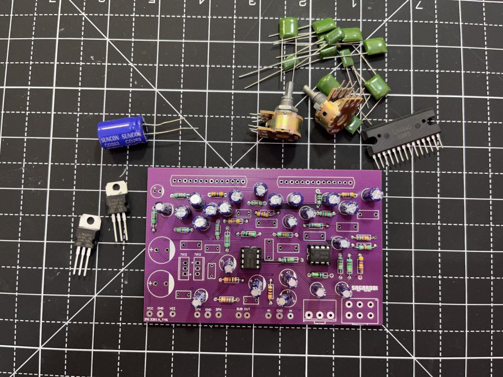
Components Required:
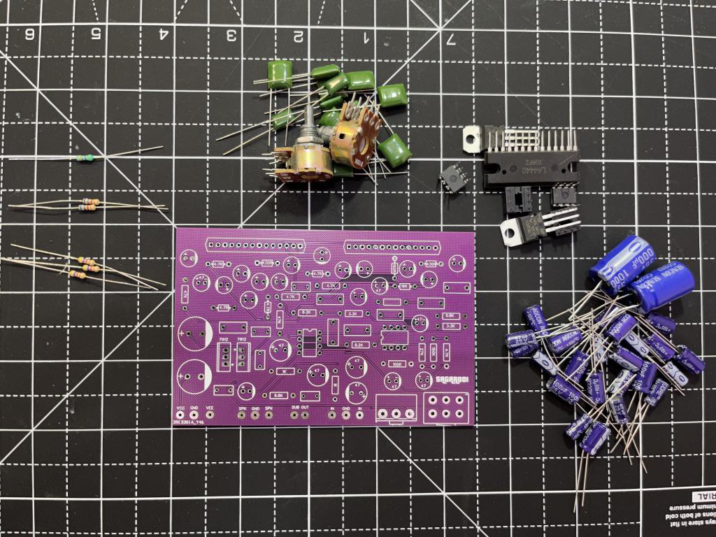
1) LA4440
2) LM4558
3) 4.7R, 4.7R, 1K, 4.7K, 6.8K, 8.6K, 16K, 47K, 100K and 150K
4) 100nf and 10nf polyester film capacitor
5) 100uf and 47uf electrolytic capacitor
6) 100k and 47k potentiometer (volume and bass respectively)
7) Custom PCB form JLCPCB
Circuit diagram:
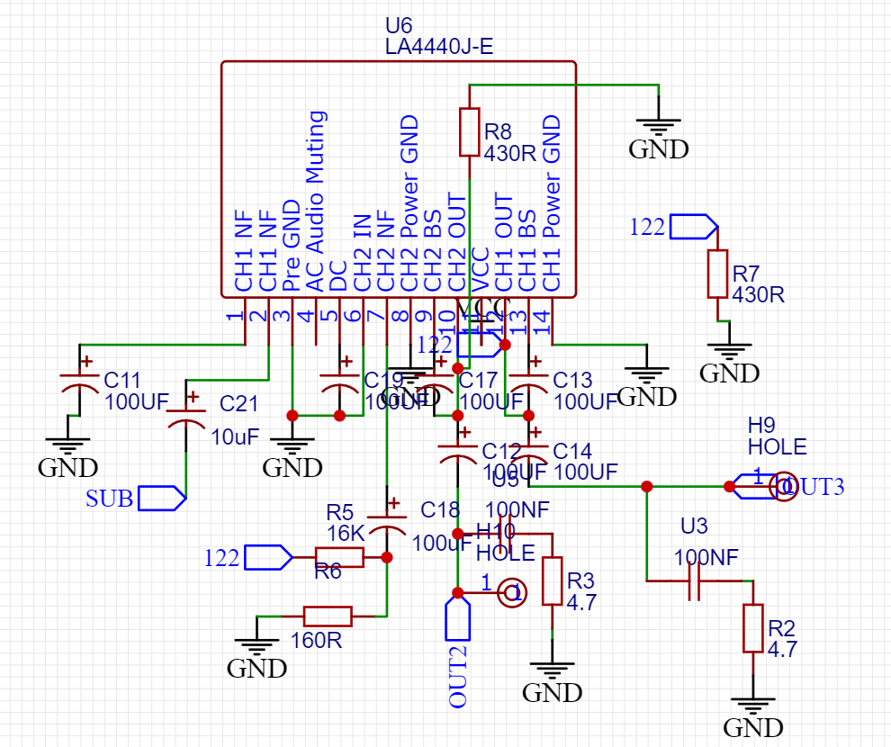
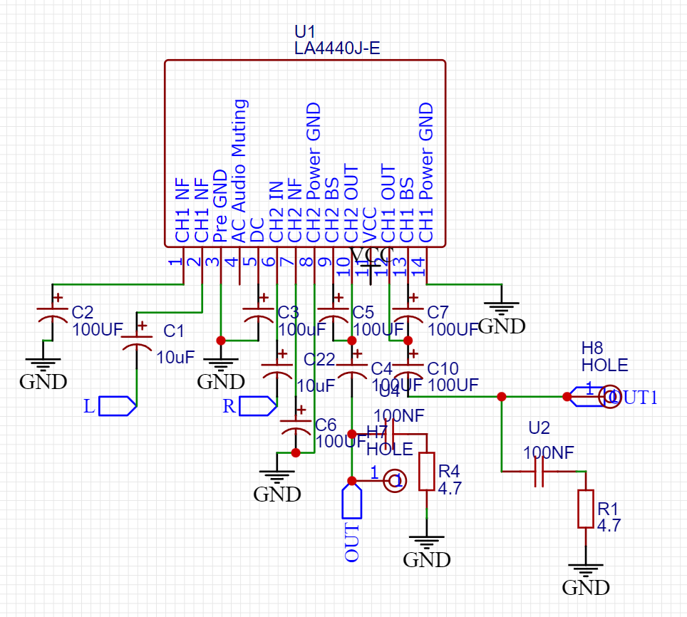
I modified the datasheet circuit and added external preamplifier circuit there to control the volume and bass. The preamplifier is used to increase the amplitude of the input signal. Here two LA4440 amplifier ICs are used one in the stereo form and other in bridge. The bridge channel is used to provide the bass. This circuit also works on a dual channel power supply that can be archived using center tapped transformer.
Preamplifier used:
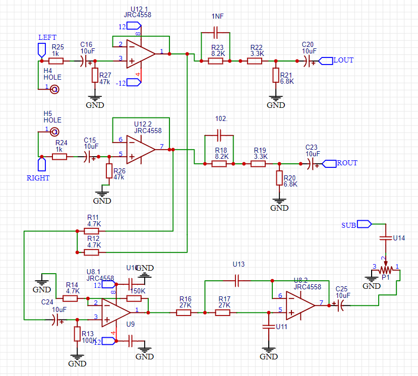
I used a 2.1 channel amplifier which can output two stereo channels and a bass. This will make a surround sound in a low cost which can be feel. The bass output is paired with both of channels which deliver a good performance to low frequencies. For preamplifier 4558 operational amplifier is used, one as the buffer and other as the low pass filter.
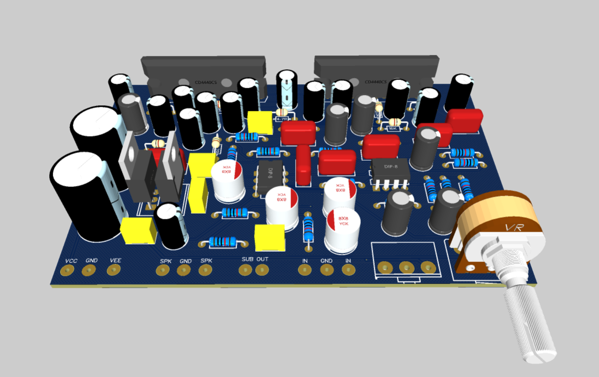
Gerber files and PCB:
Then I designed the PCB files using EasyEDA and exported them as Gerber files. These Gerber files can be used to place order from JLCPCB. I am using JLCPCB prototyping service for my designs for more than 2 years because it is the most affordable and reliable service available in just $2 for 5 pcs.
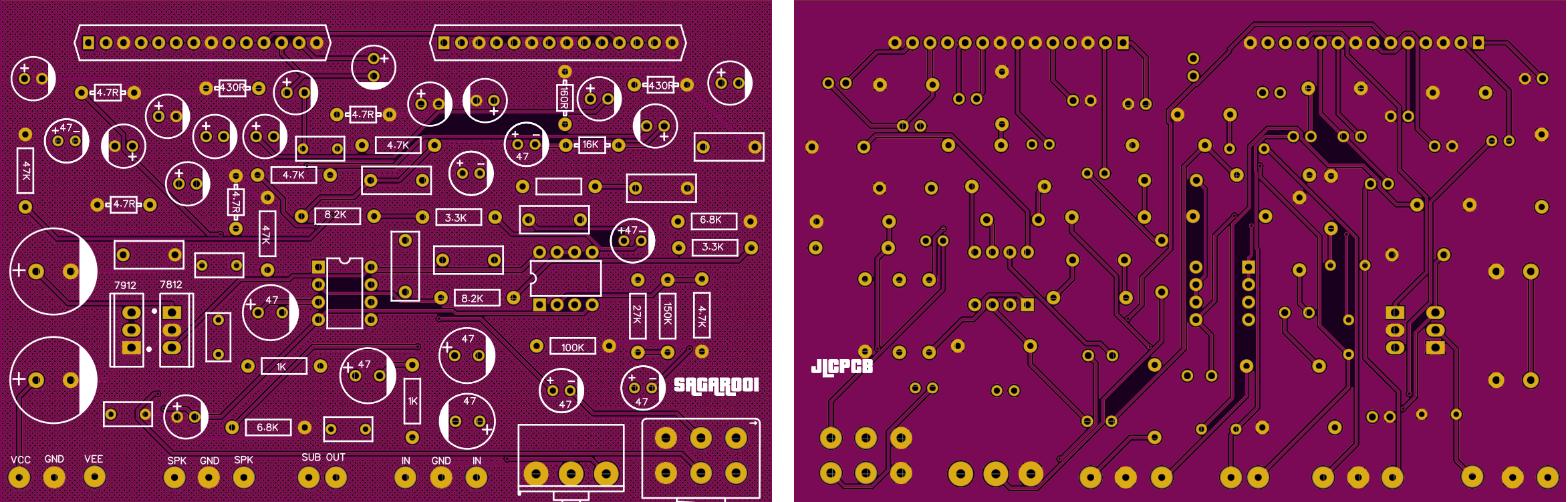
I used purple color, HASL finish, FR4 material and 1.6mm thickness, you can download the same files from here if want to use this design. Register to JLCPCB and get $54 new user coupon.
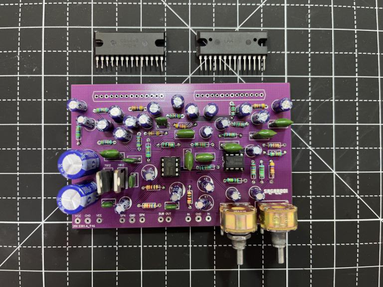
Soldering and assembly:
First of all, I recommend to solder low form factor components like resistor and diodes. After that you should go with capacitor and then for the main ICs. The filter capacitors are quite big in size which is mounted in the last. Solder properly using solder paste because any dry solder joint may produce uneven output and Hum.
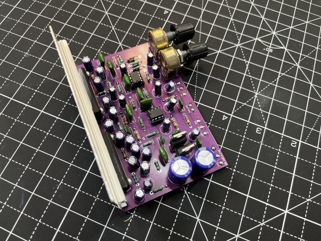
Mounting heatsink:
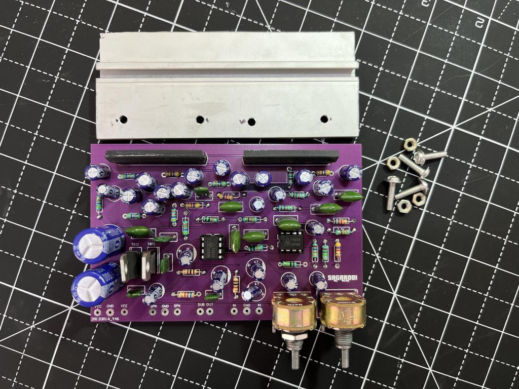
The amplifier runs hot when working on the peak performance. While 19watt max output did not dissipate a lot heat and can be controlled using a single piece of heatsink. Here I am using a custom heatsink piece which is around 100x30mm and no need of external fan with this amplifier.
Working of amplifier:
This is a 2.1 amplifier and the audio test is shared below. In the amplifier a lot of capacitor are used which is way too high for a low output. The circuit is properly designed using the datasheet and just modified the preamplifier section. The audio output on stereo channels in amazing but the bridge channels have a little distortion. Stereo channels are loud enough to make noise in large assembly hall. The low frequency output is not stable enough to drive any subwoofer at all. But a small bass with high speaker output can be used in systems like assembly hall purpose.
More modifications and upgrades:
The stereo is working great as stated above and next time I will modify the bridge bass channel by integrating the same circuit TDA2050 dual IC which gives a max subwoofer output of 50watts. Then using the same preamplifier section, I will test the bass. This amplifier designed is just a practice you can try more configuration all the schematics are shared in the description and embedded links in the post.