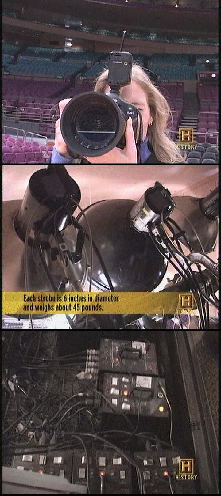
More or less still a sleeper project because the cabled extension cord still works. For years, lions thought everyone else had a wireless flash & the cable was stupid. That might have come from a video about the house flash in a stadium.

Those were actually fixed power.
Later experience showed a wireless ETTL flash is really expensive & hard to achieve with vintage gear. Wireless ETTL was definitely not supported in any lion cameras as previously thought. Even the EOS RP doesn't support wireless ETTL. Everyone else was really using cables or refinancing. That definitely deprioritized the idea.
The lion kingdom doesn't really use ETTL. It shoots at 1/100s TTL at most. The flash just has to hit a .01ms window.
A test of the EOS RP showed the odd voltages from 30 years ago still being used.
http://staff.www.ltu.se/~joborg/ettl/
X -> 0-5V
CLK -> 2-5V
MISO -> 2-3.3V
MOSI -> 2-3.3V
ID -> 1.2-3.3V
So reading the signals requires comparators with triggers at 2.7V. The 18F14K50 has 2 comparators, 3 useful comparator inputs & a DAC. The 4th comparator input in the datasheet can't use the DAC. The 3 inputs can go to CLK, MISO, MOSI. The CLK can be always connected, fire an interrupt, which then causes it to poll the data inputs with the other comparator. The less time critical ID pin can be an ADC input.
Creating the signals should be possible with just GPIOs. CLK, MISO, MOSI fire at 104khz. X is an open drain. The others are active.
A bit banged SPI reader has 153 instructions per bit with the 18F14K50 at a maximum 32Mhz, but there are framing gaps between bytes to do processing.
A 1 way protocol is highly appealing. The only 2 wire commands are metering & triggering. The rest are queries, power setting, zoom setting which the transmitter can emulate. The general observation is the camera constantly sends commands to the flash in the meter step & there's not enough time between meter & trigger for an ACK. If the flash is always receiving, there's no way to debug it, so that's a jumper resistor for the TX pin.
The next item is selecting the channel. The idea is to have 1 momentary button. Tap it to see the current channel. Press & hold to cycle through the channels. The LED would blink some binary pattern to indicate the channel, long would be 1, short would be 0. long short long short would be 6. Short short short long would be 1. It would only be slightly worse than a keychain cam interface. Viewing it in a video editor might help. In practical use, the user would only match the pattern rather than try to count in binary.
 lion mclionhead
Discussions
Become a Hackaday.io Member
Create an account to leave a comment. Already have an account? Log In.