 lion mclionhead
The next step was simulating the flash for the camera. The journey begins with driving the DAC connected to D1 to simulate the "from flash" signal. Apparently, it expects D1 to be held on the last bit for a while, then lowered for a while to signify busy, then raised as a form of flow control.
Helas, the packets from the camera are not constant length as they were when using the real flash. There are insertions, deletions, & transpositions. It somehow knows the flash is simulated despite getting a byte for byte replica.
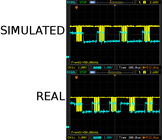
The real flash has variations in the length of its busy period but it actually looks like the camera has a minimum break between bytes. It was confirmed to definitely wait for the CLK to go low & high by simulating very long busy periods.
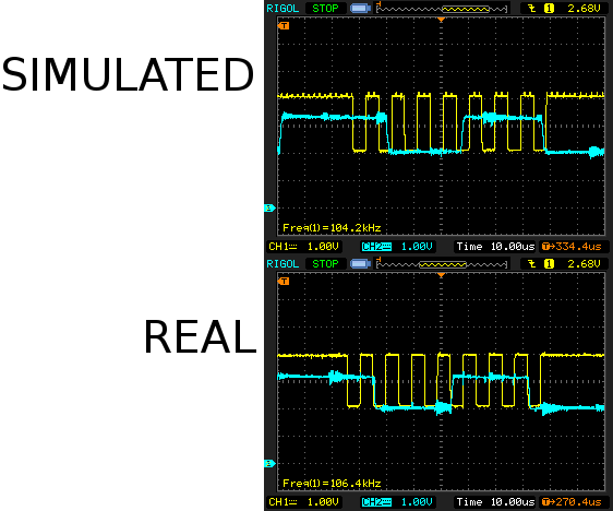
But more importantly, the real flash has transitions right on the falling edge while the simulated flash is right against the rising edge. It's probably seeing data corruption from the simulated flash. The simulated flash reads back its own data using its own delayed ADC so it doesn't see the data corruption.
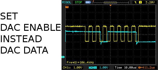
Then a lion realized it might be faster to flip the GPIO between analog & digital to get it to change between 2V & 3V faster. This is only possible on the STM32 by enabling & disabling the DAC. This did indeed buy just enough time to eliminate the glitches. It actually went through the full metering & exposure with simulated packets. More margin could be bought with overclocking.
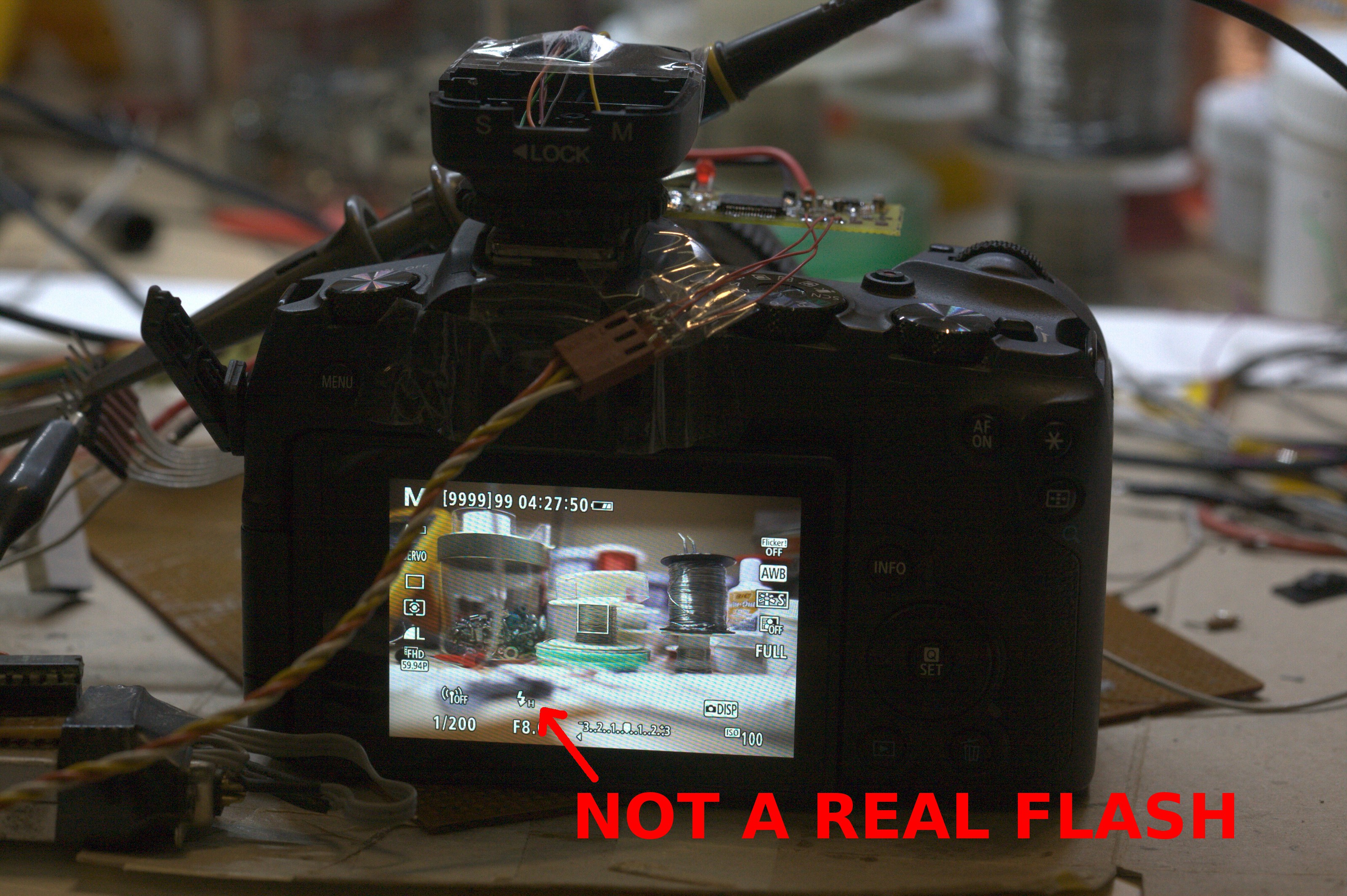
An electronically simulated flash was a big step towards wireless, converting a vintage flash to ETTL, & building custom flashes. The next step is simulating the camera for the flash.
Discussions
Become a Hackaday.io Member
Create an account to leave a comment. Already have an account? Log In.