 Lithium ION
Dc power meters are really very essential tool for every electronics hobbyist. Dc power meters are used for monitoring voltage and current ratings simultaneously and thus calculate the power by multiplying. Our microcontroller with an ADC can measure the voltage but to measure the current we need some external circuitry. Which can change the current into voltage form and then measure the ratings. There are many current sensors are available in market based on shunt regulator and hall effect.
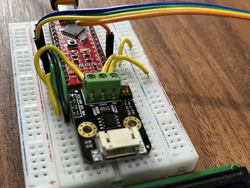
The high precision is given by a dedicated power wattmeter IC. Because homemade shunt resistor may have uneven drop across the length. Then I got this INA219 Wattmeter sensor from DfRobot. It is the smallest and most compatible sensor, which can give precise readings with its own library.
This project is sponsored by PCBWAY – A one stop solution for a hobbyist working on electronics projects. PCBWAY provide services like SMT assembly, PCBA, 3D printing, Stencil and metal CNC. Check more on the official website PCBWAY.com. Participate in the contest initiated by PCBWAY and get exciting rewards.
INA219 Wattmeter:
Gravity I2C Digital Wattmeter is a high-resolution, high-precision, large-scale measurement module that can measure the voltage, current and power of various electronic modules and electrical equipment within 26V 8A, and the maximum relative error is less than ±0.2% (A simple manual calibration is required before usage).

The module adopts TI INA219 zero temperature drift current/power monitoring chip and 2W high power low temperature drift 10mΩ alloy sampling resistor. The voltage and current resolution can reach 4mV and 1mA respectively. Under the full-scale measurement condition, the maximum relative error of voltage and current measurement is lower than ±0.2%. It provides also four I2C addresses that can be configured via the 2P DIP switch. The module accurately measures bi-directional high-side currents (current flowing through the power supply or battery positive), which is especially useful in solar or battery fuel gauge applications where the battery needs to be charged and discharged. This status can be simply determined by positive or negative current readings.
Specifications:
- Input Voltage (VCC) : 3.3V to 5.5V
- Voltage Range (IN+ or IN- relative to GND): 0 to 26 V
- Voltage Resolution: 4 mV
- Voltage Relative Error: <±0.2% (Typical)
- Current Range: 0 to ±8A (Bidirectional current)
- Current Resolution: 1mA
- Current Relative Error: <±0.2% (Typical, manual calibration required)
- Power Range: 0 to 206 W
- Power Resolution: 20 mW (Hardware) / 4 mW (Software)
- Quiescent Current: 0.7 mA
- Interface: Gravity I2C (logic level: 0-VCC)
- I2C Address: Four options 0x40, 0x41, 0x44, 0x45
Components Required:
2) Arduino Nano
3) 16x2 LCD
4) Power supply
5) External Load
6) Custom PCB from PCBWAY
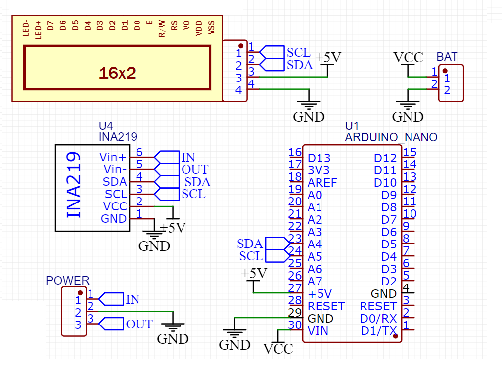
Circuit diagram:
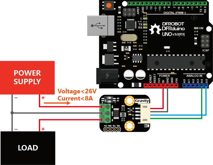
Wattmeter sensor and the LCD both are compatible with Arduino I2C bus. With different address you can plug up to 127 devices to this but here we are using only a sensor and LCD. VCC is connected to 5volts, GND is common to all, SCL to A5 and SDA to A4 of Arduino. The microcontroller is directly powered by USB. A PCB prototype shield is given below where you can directly plug the electronics and we are ready to go.
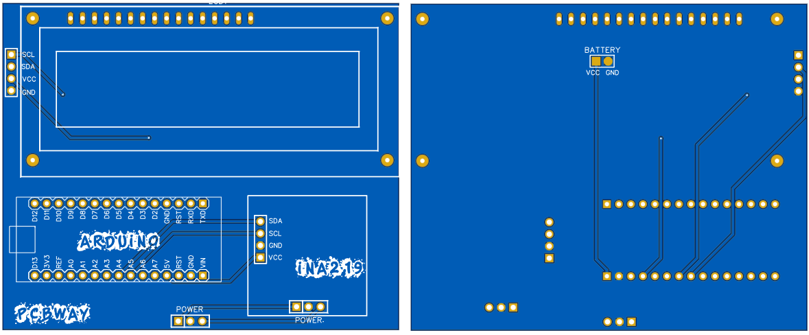
Gerber files and PCB specs:
In this PCB shield Arduino, LCD and wattmeter sensor can be plugged directly. Arduino voltage regulator is enough to get a linear 5v for the external circuitry. Battery connection are given at the bottom layer, so it can be directly powered using +12v or +9v battery. Download all the required schematics and PCB files from here.
PCBWAY is the China’s leading PCB manufacturer from where you can get the project PCB prototypes in really amazing price of $5 for 10pcs. Quote now and register using this link to PCBWAY to get free new user coupons.
Arduino Code:
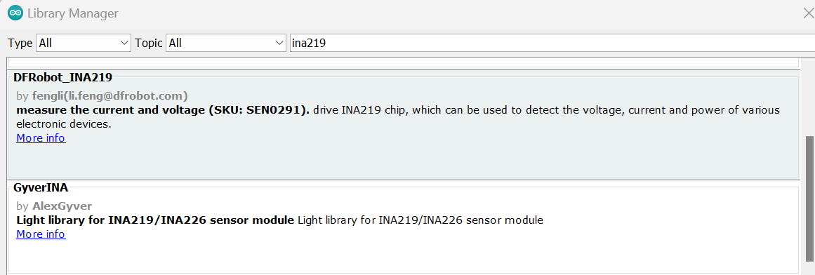
Download LiquidCrystal_I2C and DFrobot_INA219 library from the...
Read more »
 gokux
gokux
 CentyLab
 John Loeffler
umm, 8 amps? pity not rated up to 20 amps.. is that do-able.. please?