 Scott
ScottThe foundational base for this project required some sort of oven. From the design perspective, I needed an oven, preferably one with a good heat-up slope, a temperature sensor, a solid-state relay that was capable of handling “house-hold” voltage and at least 20 amps of current and a PID controller.
Oven selection: There are plenty of “toaster ovens” manufactured by various manufacturers available all around the world. The oven must be able to attain and sustain at least 230°C, which is about 450°F. However, in testing some of the ones I had access to, they had a poor heat-up slope. For use as a reflow-oven, a slope of 1°C to 2°C is adequate but an oven that can attain and sustain 260°C (500°F) is needed. The higher the heat-up slope, the better. On oven with four heating elements is best; two on the top and two on the bottom is great because it increases the heat-up slope. Also, a small interior is best as the models with the larger interior take too much time to heat up and had a low heat-up slope.
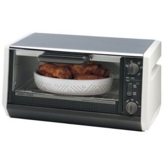 BLACK & DECKER Model TRO355
I happened to have a relative that decided she wanted to upgrade from her “dinky” toaster oven to one a bit larger. Perhaps one that could fit a pre-made 12 inch pizza? She “gifted” her old one to me, which was like new. I mean, it looked like it had never been used and perhaps it never had. It was a BLACK & DECKER Model TRO355. It boasted 1550 watts of power usage, which translated to good heat generation capability. In testing, I found that it performed with a heat-slope of on average, 1.5°C per second. It has 4 heating elements, top and bottom and a small cavity. In testing, it was able to attain and sustain about 275°C (525°F). Perfect for my use.
PID controller: The PID controller is the most important piece of the reflow-oven because it has to accurately detect the temperature and constantly adjust it to maintain the desired solder profile. The PID controller has to take into account the rather slow response of a heating and regulating the heat in the target environment. It has to “source” heat into the environment and effectively monitor the environment’s ability to “sink” (cool) heat out of it, accurately regulating it all the while to maintain a stable temperature within said environment. PID controllers are heavily used in chemical and industrial manufacturing processes. As a matter of fact, there has been much information published about how the PID (Proportional-Integral-Derivative) algorithms work and how to calibrate a PID controller for any particular application, which for an industrial application, can sometimes take hours, days or even weeks to stabilize.
 Various PID Controllers
In my research, I looked into several low-cost “stand-alone”PID controllers but they were intended to regulate a single temperate with only one “set point”, perhaps two. I needed one that was adjustable and programmable, so I gave up on that type. With that avenue being a dead-end, I started looking into what I would need if I wanted to build my own. As I stated earlier, there were a few sources available on the Internet. Mostly college students that were designing reflow-ovens for their semester-end projects and for use in the college lab.
 TECHFX Reflow Controller
I did find a unit by TechFX that seemed to have everything I needed and was based on a PIC processor. The PCB was fairly inexpensive, about US$25. In testing with my B&D oven, I found that it was not stable and did not perform well. A suggested firmware update by the OEM didn’t help either. At the time, I was romantically involved with a female applications engineer who had worked in the pharmaceutical industry designing and maintaining process controls. She used to work for two of the leading high-end industrial PID controller OEM’s. While employed for one of them, she wrote a technical brief detailing an “easy way” to calibrate PID controllers “in the field”. I would say that she was “an expert” on the subject and even she came to the conclusion that the PID algorithm was dysfunctional! Needless to say, I had a lot of questions about the unit, which I was able to ask via email but eventually, being unable to solve my problems, the support guy got verbally abusive towards me, telling me things like “a 12-year old child can calibrate this unit!” and “are you stupid?“. He was geographically located about 2 hours away from me and at one point, because I was concluding that his product was defective and wanted a refund, which was refused for the reason of “the unit is used“, he threatened me saying “I’ll come find you and kick your a**!“. Wow! VERY unprofessional … and scary! At this point, I will state this disclaimer; apparently, this product is still being sold and at this point, it is probably a functional and mature product. In all likelihood, the tech support guy probably doesn’t even work for them any longer.
 ROCKET SCREAMReflow Oven Controller Shield
With the TechFX Reflow Controller on the scrap-heap and without a refund in hand, I started looking for another solution, preferably AVR-based. What I found was the ROCKET SCREAM Reflow-oven Controller Shield, which is ARDUINO compatible and thus a perfect choice for me. At US$38, it was a little more expensive but my options being limited, I ordered one and awaited its arrival from Malaysia. The “shield” comes with an 8×2 LCD but I did not use it. At the time I purchased this “shield”, ROCKET SCREAM was a small startup and just getting started with it. It was a new product for them but the support was great and the proprietor was kind and courteous, always willing to assist when and where he could.
Temperature Sensor: With the perfect oven in my possession, I started looking for a temperature sensor that could withstand the high heat environment that it would need to monitor. This meant that the temperature sensor had to be mounted inside the oven. Toaster ovens use a thermo-mechanical method of determining just when to cut off power to the heating elements. The sensor is mounted on the inside wall of the inner oven panel that separates the dials from the interior of the oven. Its one reason why these low-cost toaster ovens are not too good at temperature accuracy and heat regulation.
 Type-K Thermocouple
The recommended thermocouple was a “Type-K”. What I eventually found and used was recommended by another article I found on the Internet. I see that ROCKET SCREAM carries them here. This particular thermocouple has a fibre-glass jacket, has an 18 inch lead and is rated from -73℃ to +482℃, well within the temperature range I needed. It was cheaper to purchase a 5-pack than to purchase 2 individually, so I ordered 5 of them.
 Solid-state Relay
Solid-state Relay: The solid-state relay (SSR) is used to switch the house-hold power to the heating elements. It is controlled by the PID controller, which typically uses an adjustable duty-cycle waveform or better known as “pulse-width-modulation” (PWM). I found an SSR at the local “surplus” store. Now, electronic surplus stores are very rare these days and having one that is located within 10 miles if you is even more rare. They had a few different ones but in looking at their “surplus stock”, I found one that was rated for 250 VAC at 25 A with a 3-32 VDC activation input.
 ROCKET SCREAM “Mini-Ultra”
AVR controller: I already had an ARDIUNO Deumilanove that I had planned to use for this project and the PID shield was “ARDUINO compatible”, so that was a match. I prefer to program AVR’s because I have been using them since 1998. In earlier years, I was a “dist-FAE” for MARSHALL INDUSTRIES and ATMEL was one of my support lines, so I am very familiar with them and have the needed development tools to code, program and debug them. When the package arrived, unbeknownst to me, the proprietor of ROCKET SCREAM had added a few “Mini-Ultra” bare PCB’s in the package with my PID shield. It was a kind gesture and an unexpected bonus that allowed me to spare my Deumilanove. The “Mini-Ultra” lacks any kind of USB-to-serial interface on it but provides a 5-pin connector for use with an FTDI USB-2-Serial bridge or the like. I already had acquired a few SILICON LABS CP2102-based USB-2-Serial bridge modules off of eBay and had them on hand for this project. I planned to use one of them with the “Mini-Ultra” to allow me to capture performance information and to supply power to the electronics … and of course, upload new firmware to the AVR.
 PID algorithm
PID library: Now having the AVR controller, PID controller shield, thermocouple, SSR and toaster oven in hand, I still needed software to implement the PID function. During my research, I came across a few different software libraries for use in AVR and PIC-based PID controllers. ROCKET SCREAM also provides schematic, PCB artwork and a sample PID “sketch” for use with their reflow shield here. The PID library is based on Brett Beauregard‘s PID library for the ARDUINO. I started out with the basic sketch but found that I needed to tailor the P, I and D parameters to my oven, which was expected based on the articles I had read. I also wanted to have an LCD on my unit so I could see certain information like current temperature, heat slope and remaining time of the current phase of the profile.
There’s also a good article here on ROCKET SCREAM’s web site that discusses what type of toaster oven to use for a reflow-oven, convection or infrared.
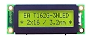 16 x 2 LCD
LCD selection: I wanted to have a display on the unit so I could monitor the reflow progress through each phase of the solder profile. Originally, I was going to use a 24×1 LCD that I had on hand but I found a problem communicating with that display. The LCD board uses the “standard 16-pin LCD pinout” so what was up? After some research, I found that this particular display uses a different HITACHI LCD controller and has a hardware strap to select 4-bit or 8-bit mode but the strap is inaccessible to the user so the LCD board is hard-wired for 8-bit mode, with no means to select 4-bit mode via software. Luckily, I had a few other 16×2 LCD modules available that were Hitachi HD44780 compatible but but they were smaller and required a bit more hacking to get a cable attached to it. There are a few libraries out there for the AVR supporting these types of displays. The chosen display module has four mounting holes on each of the 4 corners, which was perfect for mounting on the front face of an enclosure.
Enclosure selection: Of course, I needed some sort of housing for the “Mini-Ultra”, PID controller shield, “start button” and LCD. Since I had it on hand, I chose to use the 6 x 3 x 2 inch RADIO SHACK project box for the enclosure. I then used a CAD program to create blocks for each of my “modules”, complete with mounting hole locations and sizes. Once I had all my “parts” created, I could locate the modules inside the enclosure with confidence that everything would fit. I printed a drill template for each of the three faces I was going to cut and taped them to each side. I drilled the round holes and used a drywall cutting bit made for the DREMEL-type tools as a router bit mounted in my drill press. Cutting those rectangular holes was a breeze! I wish I had recalled I had these bits for the last three plastic box cutting projects I did!
Discussions
Become a Hackaday.io Member
Create an account to leave a comment. Already have an account? Log In.