Close
0%
0%

2022 Hackaday Supercon 6 Badge Guide

This is the starter guide for the 2022 Hackaday Superconference badge, designed by Voja Antonic.

Similar projects worth following

Modern computers offer gigabytes of RAM and more processor cores than we have fingers to type with. But as we all know, a hacker isn’t defined by the tools at their disposal, but rather the skill and imagination with which they wield them.

So this year, we’ve taken a slightly different approach. Rather than try and cram the badge with even more state of the art hardware than we did in 2019, we’ve decided to go back to the well. The 2022 Supercon badge is a lesson in what it means to truly control a piece of hardware, to know what each bit of memory is doing, and why.

Make no mistake, it’s going to be a challenge. In fact, we’d wager most of the people who get their hands on the badge come November 4th will have never worked on anything quite like it before. Folks are going to get pulled out of their comfort zones, but of course, that’s the whole idea.

We have an extensive tutorial for you below.  Start here!

Tools, including the assembler, emulator, and a bunch of example code can be found in the Supercon6 Badge Tools Github repo.  (Pull requests welcome!)

There's an online assembler as well!

And if you want to know absolutely everything about the badge, you will find it in Voja's extensive documentation PDF, found here:  Official Badge Page - Technical Deep Dive

  • 1
    Badge Basics

    Imagine it's the summer of 1975. A warm breeze blows through the window as you carefully slide the cover over the Altair 8800 you just finished building. You look down upon the rows of LEDs and switches, and realize with a sense of pride that you're likely the only person in your town that owns their own computer. You're truly living in the future, like Captain Kirk himself.

    There's only one question now...what the hell do you do with it?

    Just like those brave souls who sent away for their own Altair kit after seeing it in Popular Electronics, you're probably wondering just how you'll put your new high-tech toy to use right about now.

    Don't worry, it's perfectly natural to be a bit confused. After all, it doesn't look much like any computer most of us have used in our lifetime. But make no mistake, it is a computer, and once you've learned how to use it, you'll be amazed at what it's capable of.

    Speaking the Language

    While we've gone through considerable trouble to develop an assembler and emulator that will let you write and test code for the Supercon.6 badge using your modern computer, we believe there's a great benefit to entering a few programs directly on the badge itself using nothing but the buttons on the front panel.

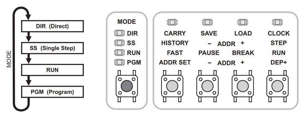
    To begin, turn the badge on by pressing the power button on the back. Then press the Mode button on the bottom left until the LED next to PGM lights up.

    This puts the badge into programming mode, where you'll enter instructions directly by using the three sets of four buttons, labeled OPCODE, OPERAND X, and OPERAND Y. To the extreme right you'll see a button labeled "Data In", and if it isn't already, you'll want to press that until the LED next to BIN lights up. This will allow you to use the buttons to directly toggle binary bits, with each lit LED counting as a 1, and each dark LED a 0.

    For example, to enter in the binary sequence 0010 0100 1100, the LEDs should look like so:

    To actually enter the 12 bit instruction into the badge, you would press the button labeled DEP+. This will clear the LEDs over the rest of the buttons, resetting them for the next instruction. The - ADDR + buttons can be used to step through the code line-by-line, allowing you to verify and correct any previous entries.

    Additional Modes

    For the purposes of this document we're largely concerned with the PGM (Programming) mode, but before we move on, a few words should be said about the badge's more advanced functions.

    DIR (Direct)

    In Direct mode, you're able to save and load programs from both the badge's internal flash and another device over a serial connection. It also allows you to experiment with various parts of the CPU, such as the Accumulator, X and Y Registers, Adder/Subtractor, Logic Group, and Flags. In this mode, instructions can be executed using the Clock button.

    For more information on DIR mode, consult pages 18 - 22 of the manual.

    SS (Single Step)

    In Single Step mode, you can execute an entered program one instruction at a time. This is invaluable for debugging, as the LEDs on the badge will allow you see exactly what's happening inside of the CPU and in RAM. If your program isn't working as you expected, going through it in Single Step mode will likely help you figure out why.

    For more information on SS mode, consult pages 23 - 25 of the manual.

    One Small Step

    Now that we have the basics out of the way, let's now enter a complete instruction into the badge and execute it.

    With the badge in PGM mode, we'll first clear any existing instructions by holding ALT and pressing both ADDR buttons together. Now, making sure the "Data In" selector on the bottom right of the badge is set to BIN, configure the LEDs as follows:

    This corresponds to the following instruction, which will place the number 7 into the register R9:

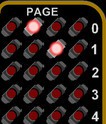
    After confirming the correct LEDs are lit, press the DEP+ button to deposit this instruction. Note that the LEDs over the buttons should turn off in preparation for the next instruction. Instead, press the MODE button until the LED next to RUN lights up, and then press the button labeled RUN. If you've done everything correctly, the LEDs on the badge should appear as they do in the image on the right.

    There's actually a lot of information packed into these handful of LEDs, but for now, the important thing to note is that there are three red LEDs lit up on the right side of the LED matrix, next to the number 9. This indicates that, as per the instruction we entered, the number 7 (0111) has been stored in register 9.

    Congratulations, you've officially run your first instruction on the 4-bit Supercon.6 badge! Feel free to take a break, and perhaps show off your accomplishment. When you're ready, move on to the next lesson, and let's see if we can do something a little more interesting.

  • 2
    Mathematic Operations

    If you've made it this far, we'll assume you understand the basics of entering binary instructions into the Supercon.6 badge and executing them. Now, we're going to ramp things up a bit by chaining multiple instructions together into actual programs.

    At the same time, we're going to start introducing new instructions which will aid you on your journey. There's a total of 31 opcodes, and while this basic introduction won't cover all of them, you should know just enough to be dangerous by the time we hit the end.

    For now, let's start off with doing some basic math.

    Registers

    Before we get to the hot digit-on-digit action, we need to talk about something pretty important: registers.

    In modern parlance, you might think of these as variables. But it's more accurate to say that they are locations in memory where data can quickly be stored and recalled by the CPU. The 4-bit CPU in the Supercon.6 has 10 General Purpose Registers (R0 through R9), and a whole bunch of interesting Special Purpose registers that we won't get into right now. (Don't worry, there's a whole manual just for them.)

    Most instructions will take at least one register as an argument, and some are actually hard-coded to only work with R0. That means to get anything done, you'll need to get comfortable with swapping data between registers.

    With that out of the way, let's see how we can use registers to actually get things done on the badge.

    Addition

    Beyond a literal one-liner, the following is one of the simplest programs possible: we're going to add two numbers together, and view the result. The code for that looks like this:

    1001 0000 0010        mov r0, 2       ; Put 2 into R0
    1001 0001 0010        mov r1, 2       ; Put 2 into R1
    0001 0000 0001        add r0, r1      ; Add the two registers

    On the left, we have the binary sequences that you can enter directly into your badge (go ahead, give it a shot), the center has the equivalent code in assembly, and finally to the right we have some descriptive comments.

    After running this program, the badge's matrix should look like image on the right. The four LEDs on each row correspond to the 4 bits held in each register, so the binary sequence in row 0 (0100) means the number 4 is currently in R0. The second row of LEDs (0010) show us that 2 is in R1.

    Logically you might have expected the answer to our little addition program would have popped up on a third row, but the add instruction only takes two registers, so that's all we've got to work with. Generally speaking, the result of any operation is going to be held in the first of the two registers, so in this case, we're left with a 4 in R0 and a 2 still lingering in R1.

    Now, the astute reader may have noticed that in this program (much like in the single instruction demonstration from the previous lesson) we didn't give any command to actually output our result to the LED matrix. That's because the matrix isn't actually a display in the traditional sense -- it's a window into the working memory of the badge's CPU.

    The matrix can be used as a display by carefully manipulating the memory within its purview, which is something we'll get to later. For now, we'll just be directly viewing the contents of the registers.

    Subtraction

    As you might expect, subtraction looks a lot like addition:

    1001 0000 1100        mov r0, 12      ; Put 12 into R0
    1001 0001 0111        mov r1, 7       ; Put 7 into R1
    0011 0000 0001        sub r0, r1      ; Subtract R1 from R0

    Running the program on your badge, we see that the LEDs next to R1 (0111) once again show that it's left with its original value of 7, while the LEDs for R0 (0101) show the result of 12 minus 7 to be 5.

    Increment/Decrement

    As you start to write more complex programs, you'll often find the need to add or subtract 1 from a register -- such as when you want to keep track of how many times a loop has gone around. In fact, it's such a common task that the CPU has dedicated inc (increment) and dec (decrement) instructions for it.

    Consider the following program:

    1001 0000 0010        mov r0, 2     ; Put 1 into R0
    1000 0001 0000        mov r1, r0    ; Copy R0 to R1
    0000 0010 0000        inc r0        ; Add 1 to R0
    0000 0010 0000        inc r0        ; Add 1 to R0
    0000 0011 0001        dec r1        ; Sub 1 from R1

    First we place 2 into R0, and then in the next line copy that over to R1, making them equal. We then run inc on R0 twice, and dec on R1.

    When you run the program and look at the LEDs, you'll see that R0 now contains the result of 2 + 1 + 1, or 4 (0100). R1 on the other hand is down to 1 (0001), since we subtracted 1 from the original 2.

    Technically you could accomplish the same thing with the add and sub instructions, but in those cases, you'd need to provide a second register that contained 1. On such a constrained system, that's a big ask, which is why the inc and dec instructions are so valuable.

    Multiplication

    On the other side of the spectrum, multiplication is something you'll do relatively infrequently. In fact, there isn't even a multiply instruction. Of course, that doesn't mean we can't do it -- we've just got to think outside the box a bit.

    For example, you might not have a command that will let you perform 5 x 3, but you can add 5 to itself repeatedly:

    1001 0000 0101        mov r0, 5       ; Put 5 into R0
    1000 0001 0000        mov r1, r0      ; Copy R0 to R1
    0001 0000 0001        add r0, r1      ; Add (5 + 5)
    0001 0000 0001        add r0, r1      ; Add again (5 + 5 + 5)

    The result (15) will light up all four LEDs on R0, which incidentally makes it the largest number we can actually handle with these 4-bit instructions. There are technically some instructions that take 8-bit numbers, which we'll get to shortly.

    Division

    Division can be done in much the same way, you just keeping subtracting the number until you hit zero. Of course, the trick there is keeping track of how many times you've subtracted the number, and checking if the result is zero or not.

    Neither of these things are concepts we've covered yet, which makes this a logical place to introduce a new topic: Program Flow

  • 3
    Program Flow

    So far, all of our programs have been only a few lines that just ran straight through. But as you develop more complex code, you'll eventually want to perform loops, or change the behavior of the program depending on the value stored in a particular register.

    While these are core programming concepts, the way they are accomplished on such a constrained system as the Supercon.6 badge might not be as intuitive as you're used to. For example, you won't find the traditional IF...THEN statements among the CPU's opcodes, but there are some equivalent instructions that you'll end up using a lot as you move forward.

    Compare and Skip

    The cp (compare) instruction does exactly what it sounds like: compares two values. But there's a bit of a trick, as this is one of those instructions that can only be used with register 0. So any time you want to compare one value to another, you'll always have to stuff it into R0 first.

    Using the cp instruction, you'll be able to determine if the given value is the same, less than, or more than what's stored in R0. This is done by checking the status of the C and Z flags after making the comparison.

    There's a few things you can do with these flags, but perhaps the most common instruction you'll use in conjunction with them is skip, which as you might have guessed, conditionally skips lines in the program based on the status of the flags.

    Let's demonstrate with a small program:

    1001 0000 1111        mov r0, 15      ; Put 15 into R0
    0000 0000 0101        cp r0, 5        ; Compare R0 to 5
    0000 1111 0001        skip c, 1       ; Skip next line if R0 < 5
    1001 0000 0010        mov r0, 2       ; Put 2 into R0
    0000 0000 1111        cp r0, 15       ; Compare R0 to 15
    0000 1111 1010        skip z, 2       ; Skip next two lines if R0 = 15 
    1001 0000 0000        mov r0, 0       ; Put 0 into R0
    1001 0001 1111        mov r1, 15      ; Put 15 into R1

    After running this program, you should see four LEDs on the right side of row 0, indicating that R0 still contains the original value of 15. That's because the two lines which would have changed it were skipped, first because the value in R0 was higher than 5, and again because it was equal to 15.

    Additionally, you should see that there are no LEDs lit on row 1. That's because the second skip instruction actually skipped two lines, not one. The ability to skip multiple instructions is definitely helpful, but keep in mind that you can only jump over a maximum of 4 lines.

    Skipping a line after a comparison might seem backwards to modern programmers -- normally the lines following an IF statement are the ones you expect to execute. But as you'll see, skipping instructions can be just as useful as executing them.

    Relative Jumps (Looping)

    While there isn't exactly a loop instruction, the 4-bit CPU is able to jump forward and backwards through the program at will, which if carefully utilized, allows you to repeat a given section of your code (or avoid it entirely).

    The following combines the jr (jump relative) instruction with inc, cp, and skip to demonstrate how the flow of a program can be controlled:

    1001 0000 0001        mov r0, 1       ; Put 1 into R0
    0000 0010 0000        inc r0          ; Increment R0
    0000 0000 0101        cp r0, 5        ; Compare R0 to 5
    0000 1111 1001        skip z, 1       ; Skip next line if R0 = 5
    1111 1111 1100        jr -4           ; Jump back 4 lines
    1001 0001 1111        mov r1, 15      ; Put 15 into R1

    There's a bit going on here, so let's walk through it step-by-step.

    First we place a 1 in R0, and then increment it. At this point, R0 equals 2. We compare it to 5, find that it's not equal, so we do not skip the jr -4 instruction. This makes the program go back 4 lines (the jr instruction itself counts as one line) to inc r0. We now have a loop that will continue until R0 equals 5.

    Once that happens, the loop exits, and our final instruction can execute. The resulting LEDs should look like the image on the right -- with 5 in R0 and 15 in R1.

    Decrement and Skip

    As mentioned previously, the inc and dec instructions are very handy, especially when combined with jr and skip so much so that there's actually a ready-made combo instruction you can use that makes things a little easier: dsz

    This instruction will decrement a given register until it equals zero, and when it does, skips the next instruction. Here's a brief example:

    1001 0000 0101        mov r0, 5       ; Put 5 into R0
    1001 0001 1010        mov r1, 10      ; Put 10 into R1
    0000 0010 0001        inc r1          ; Increment R1
    0000 0100 0000        dsz r0          ; Decrement R0 until 0
    1111 1111 1101        jr -3           ; Jump back 3 lines
    1001 0010 1111        mov r2, 15      ; Put 15 into R2

    In this example, we increment R1 while we decrement R0, with a jr instruction to continue looping around until dsz sees that R0 equals 0 and skips it. The end result, as shown on the right, should be no LEDs lit on row 0, and four each in rows 1 and 2.

    As you can see, this instruction is perfect for when you want to repeat an action a specific number of times. It saves you a couple lines of code compared to doing it manually, plus you don't have to remember which flags mean what since it's hard-coded to look for the equal condition.

    Division (Revisited)

    Now that we've covered loops and conditional control of the program flow, let's tackle the division program mentioned in the previous chapter:

    1001 0000 1111        mov r0, 15      ; Put 15 into R0
    1001 0001 0011        mov r1, 3       ; Put 3 into R1
    1001 0010 0001        mov r2, 1       ; Start result counter at 1
    
    0011 0000 0001        sub r0, r1      ; Subtract R1 from R0
    0000 1111 1010        skip z, 2       ; Skip next two lines if result is zero
    0000 0010 0010        inc r2          ; Increment counter
    1111 1111 1100        jr -4           ; Jump back to division

    First the dividend (15) goes into R0, and the divisor (3) is held in R1. The program then uses a loop to keep subtracting R1 from R0 until the result is 0. We don't need to use cp here, as the sub instruction will handily raise the Z flag for us. Once R0 is empty, the next two lines are skipped so that the loop can exit.

    The final result should look like the image on the right -- row 0 will show no LEDs, row 1 will have 0011 (3), and row 2 will display the answer to our division problem: 5 (0101).

    But wait a minute...what happens if there's a remainder? Or you want to divide a small number by a larger one? Well, that's a good question, you should look into it and find out. After all, we can't show you everything here.

    That wraps up the Program Flow chapter. Next up, Hardware I/O.

View all 6 instructions

Enjoy this project?

Share

Discussions

Adrian Freed wrote 11/12/2022 at 04:09 point

Here is the first version of an assembler/code synthesizer I wrote for the badge: https://github.com/adrianfreed/Supercon6BadgeWork

  Are you sure? yes | no

Octavian Voicu wrote 11/07/2022 at 00:18 point

Here's version 0.01 of my text-based C emulator for Voja's 4-bit processor: https://github.com/voctav/voja4_nibbler

  Are you sure? yes | no

Varun Mehta wrote 11/04/2022 at 20:14 point

Here's my very silly brute force version in 20 instructions. It writes the answer to R0 and shows the original number in R2+R3. By the way it turns out the web assembler has a bug and doesn't turn the BIT instruction into machine code correctly!

;get rand
  MOV R3,0
  MOV R0,[0xFF]
  MOV R1,R0
  MOV R0,[0xFF]
  MOV R2,R0
  MOV R3,R1
  MOV R0,0
;calc xor
  XOR R1,R2

  BIT R1,0
  SKIP Z,1
  BTG R0,0
  BIT R1,1
  SKIP Z,1
  BTG R0,0
  BIT R1,2
  SKIP Z,1
  BTG R0,0
  BIT R1,3
  SKIP Z,1
  BTG R0,0


  Are you sure? yes | no

LqqkOut wrote 11/04/2022 at 20:06 point

16 Instructions, commented below. Selects two random nibbles, xors them, shifts digits and counts. End parity bit is stored in R0

MOV R0, FF       # Store Random in R0
MOV R0, R1        # Move Random to R1
MOV R0, FF        # Store Random in R0
XOR R0, R1          # Xor two halves, store in R0
MOV R0, R2        # Move R0 to R2 (store xor result)
AND R0, 0000    # Clear carry and store 0 in R0
AND R3, R0         # Set R3 to zero (did we need to initialize memory)

RRC R2                 # Shift rightmost (first) digit to accumultaor
ADC R0, R3          # Add accumulator (smallest bit) to R0

RRC R2                 # Shift second digit to accumulator  
ADC R0, R3          # Add accumulator to R0

RRC R2                  # Shift third digit to accumulator  
ADC R0, R3           # Add accumulator to R0

RRC R2                  # Shift fourth digit to accumulator  
ADC R0, R3           # Add accumulator to R0

AND R0, 0001       # Clear remaining bits

- James / LqqkOut

  Are you sure? yes | no

Octavian Voicu wrote 11/04/2022 at 19:19 point

Here is my solution for the challenge. Is this the right place to post? :)

It's 11 instructions long for computing the result, plus two optional instructions as explained below (but arguably it only needs 11 to come up with the result).

MOV R0, Rnd   # 0: D F F
MOV R1, R0    # 1: 8 1 0
MOV R0, Rnd   # 2: D F F
XOR R0, R1    # 3: 7 0 1
MOV R1, R0    # 4: 8 1 0
RRC R0        # 5: 0 D 0
RRC R0        # 6: 0 D 0
XOR R0, R1    # 7: 7 0 1
MOV R1, R0    # 8: 8 1 0
RRC R0        # 9: 0 D 0
XOR R0, R1    # A: 7 0 1
# Result is in LSB of R0.
# Optional: clear other bits of R0.
AND R0, 1     # B: 0 6 1
# Optional: loop forever to preserve result.
JR -1         # C: F F F

Edit: I'm bad at counting, corrected instruction count.

  Are you sure? yes | no

Octavian Voicu wrote 11/04/2022 at 19:57 point

One more solution that's using a loop and is only 10 instructions (plus two optional):

MOV R0, Rnd    # 0: D F F
MOV R1, R0     # 1: 8 1 0
MOV R0, Rnd    # 2: D F F
XOR R0, R1     # 3: 7 0 1
MOV R2, 3      # 4: 9 2 3
# Loop:
MOV R1, R0     # 5: 8 1 0
RRC R0         # 6: 0 D 0
XOR R0, R1     # 7: 7 0 1
DSZ R2         # 8: 0 4 2
JR  -5         # 9: F F B
# Result is in LSB of R0.

# Optional: clear other bits of R0.
AND R0, 1      # A: 0 6 1
# Optional: loop forever to preserve result.
JR -1          # B: F F F

  Are you sure? yes | no

Octavian Voicu wrote 11/04/2022 at 20:15 point

Okay, in true code golf style, I was able to shave off another instruction by moving the first XOR into the loop. 9 core instructions (+ 2 optional).

MOV R0, Rnd    # 0: D F F
MOV R1, R0     # 1: 8 1 0
MOV R0, Rnd    # 2: D F F
MOV R2, 4      # 3: 9 2 4
# Loop:
XOR R0, R1     # 4: 7 0 1
MOV R1, R0     # 5: 8 1 0
RRC R1         # 6: 0 D 1
DSZ R2         # 7: 0 4 2
JR  -5         # 8: F F B
# Result is in LSB of R0.

# Optional: clear other bits of R0.
AND R0, 1      # 9: 0 6 1
# Optional: loop forever to preserve result.
JR -1          # A: F F F

  Are you sure? yes | no

Octavian Voicu wrote 11/04/2022 at 21:20 point

Some comments on the approach:
- XOR-ing the two random numbers reduces the problem to just the parity of a single 4-bit number.
- A loop will copy the intermediary result, shift right, and XOR the original with the shifted copy.
- Some bits end up being XORed three times. TBH this was a bit of a lucky accident (thought it was a bug when I first realized), but it works nevertheless.

Let's say the two rand numbers (in binary) are "abcd" and "efgh", then the result needed is a^b^c^d^e^f^g^h.

Start:
BIT  3 2 1 0
R0:  a b c d
R1:  e f g h

After first step:
BIT  3    2    1    0
R0:  a^e  b^f  c^g  d^h
R1:  ?    a^e  b^f  c^g

After second step:
BIT  3  2        1        0
R0:  ?  a^b^e^f  b^c^f^g  c^d^g^h
R1:  ?  ?        a^b^e^f  b^c^f^g

After third step:
BIT  3  2  1        0
R0:  ?  ?  a^c^e^g  b^d^f^h
R1:  ?  ?  ?        a^c^e^g

After fourth step:
BIT  3  2  1  0
R0:  ?  ?  ?  a^b^c^d^e^f^g^h
R1:  ?  ?  ?  ?

This ugliness *could* be avoided by doing an additional XOR before the loop, duplicating the result once outside the loop, then only shifting the copy in the loop. In this case LSB of R0 will However, this is one instruction longer (10 instructions in total). The best solution I have so far is still the previous one (9 instructions), but this one is easier to reason about than the previous 10 instruction one:

MOV R0, Rnd    # 0: D F F
MOV R1, R0     # 1: 8 1 0
MOV R0, Rnd    # 2: D F F
# Compute XOR of two numbers in R0 and dup to R1.
XOR R0, R1     # 3: 7 0 1
MOV R1, R0     # 4: 8 1 0
# Init counter R2=3.
MOV R2, 3      # 5: 9 2 4
# Loop start:
# - Shift R1 right by one and XOR into R0.
# - Only LSB of R0 and the unprocessed bits of R1 matter.
RRC R1         # 6: 0 D 1
XOR R0, R1     # 7: 7 0 1
# While (--R2 > 0) repeat. 
DSZ R2         # 8: 0 4 2
JR  -4         # 9: F F C

  Are you sure? yes | no

Similar Projects

Does this project spark your interest?

Become a member to follow this project and never miss any updates