 ElectronicABC
Supplies
pcb gerber:
https://mega.nz/file/CMImHSja#DEQTrlgzDNK2NkCtMb1EFxjRpG13PJeWUPUv4Ay2hHI
SCHEMATIC DIAGRAM
Here we will see the schematic diagram used in our circuit
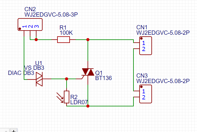
FUNCTIONING
The operation is basic when there is light or illumination the LDR will have a very high resistance so it will not activate the GATE of the TRIAC, but when it detects darkness its resistance will decrease almost to 0 OHMS and this will let the current pass to the GATE and activate the TRIAC letting the CURRENT pass from T1 to T2.
LDR
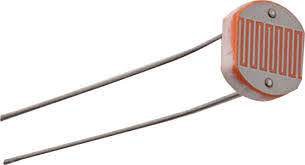
The LDR (Light Dependent Resistor) or photoresistor is an electrical resistance which varies its value depending on the amount of light that falls on its surface. The greater the intensity of light that falls on the surface of the LDR or photoresistor, the lower its resistance and the lower the light that falls on it, the greater its resistance.
How does an LDR or photoresistor work?
When the LDR (photoresistor) is not exposed to light radiation, the electrons are firmly attached to the atoms that make it up, but when light radiation falls on it, this energy releases electrons, which makes the material more conductive, and thus This decreases its resistance. LDR resistors only reduce their resistance with light radiation located within a certain band of wavelengths. The photoresistor built with cadmium sulfide are sensitive to all visible light radiation and those built with lead sulfide are only sensitive to infrared radiation.
TRIAC
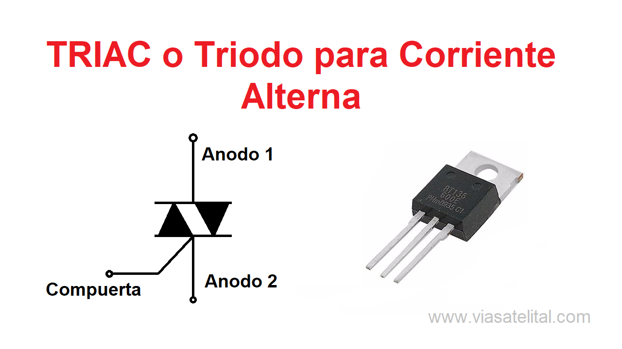
The TRIAC is a three-terminal semiconductor electronic component for current control. Its name comes from the term TRIode for Alternating Current. We could say that a TRIAC is used to control an AC (alternating current) load, similar to how a transistor can be used to control a DC (direct current) load. In short, it is an electronic switch but for alternating current. Triacs are often used as alternatives to relays.
Its basic operation is to close a contact between two terminals (anode 1 and 2) to let the current pass (output current) when a small current is applied to another terminal called "gate" or Gate (activation current).
The triac is an electronic component that is used to control the current, basically it can do the switch function of a transistor, but this component does it in alternating current unlike the transistor that does it in direct current.
How does a triac work?
The operation of this component is quite simple to understand, since it has three terminals, two anodes and a door known as a gate. The alternating current is placed in the anodes together with the element to be controlled, be it a motor, a lamp, an oven, etc. It can be anything that works with alternating current, finally once we place a current inside the gate terminal it is activated to act as a closed switch, to deactivate it just remove the current from the entire circuit
ELECTRONIC COMPONENTS
· 1 TRIAC BT136
· 1 DIAC DB3
· 1 RESISTOR 1/2W 100K
· 1 LDR
· 1 BLUE TERMINAL BLOCK 3 PINS
· 2 BLOCK TERMINAL BLUE 2 PINS
· 1 POTENTIOMETER 1Mohm
· 1PCB
FEATURES
· MAX OUTPUT CURRENT 4A
· VOLTAGE CONTROL 220VAC
· CHANGEABLE SENSITIVITY
· COMPACT CIRCUIT
· FULLY VOLTAGE CONTROLLED CIRCUIT 220VAC 60HZ
· WORKS FOR BOTH 110VAC /220VAC 50HZ/60HZ
EASYEDA
HERE WE WILL SEE THE IMAGES OF THE 3D IMAGE...
Read more »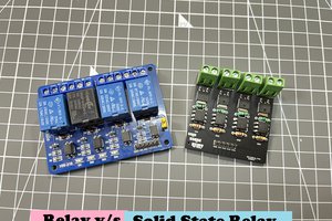
 ElectroBoy
 hesam.moshiri
 Donnie Agema
 Lithium ION