 j
j
This idea was born when i saw this project years ago: https://hackaday.io/project/170961-resistor-color-code-clock-v10
NOTE: There is a bug showing resistor values under 100 since gold nor silver can be displayed. AND the multiplier seems to be one digit / color of. I have to verify this, since i obviously still don't know the color code (;. Its an easy fix. I just have to move values from 10-99 one to the right and 1-9 two to the right. The multiplier must be shift to just one digit. Error are there to make (:
UPDATE [16.11.2022]: Code should work now as intended
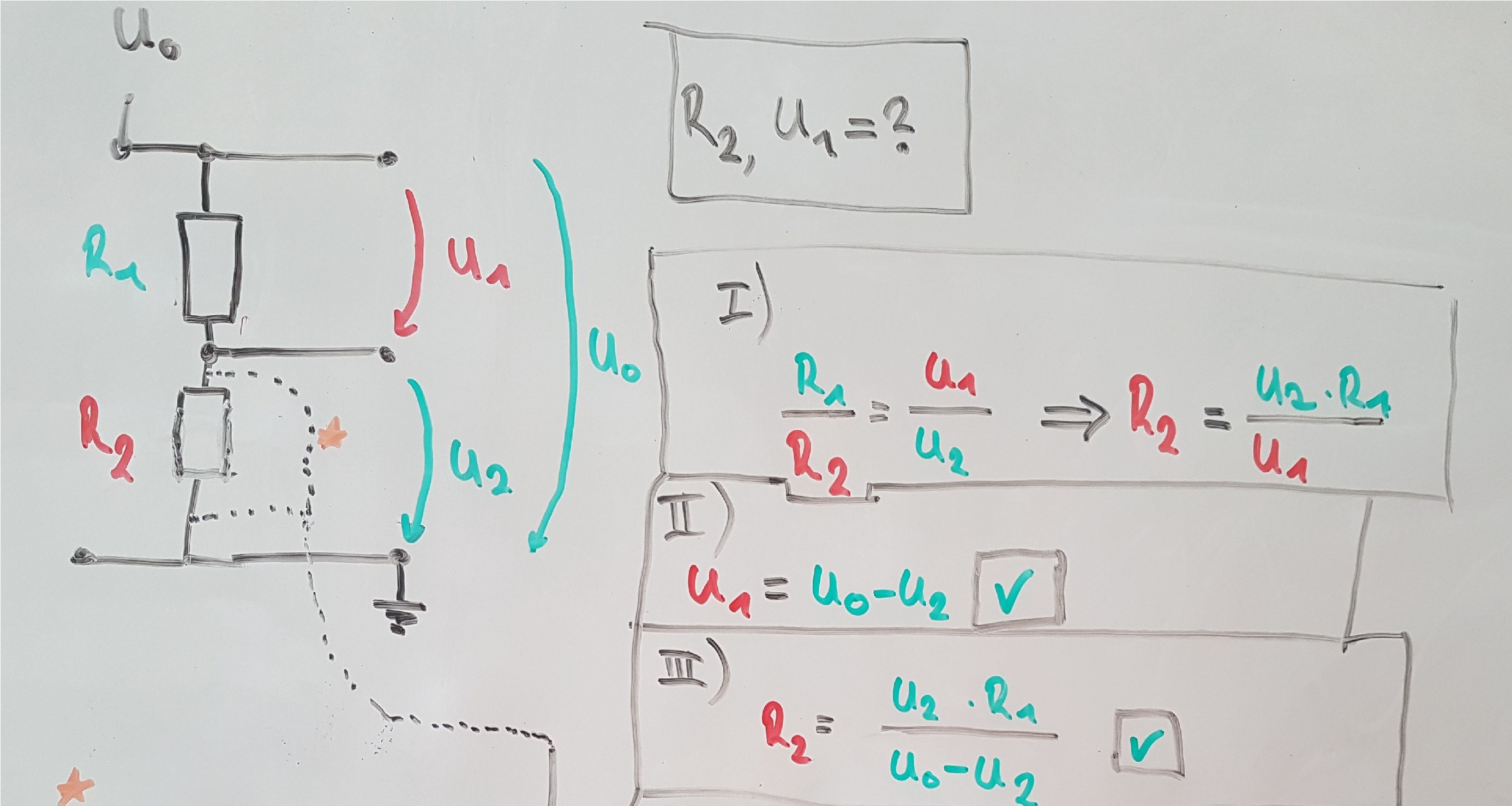
The best choice seemed to be a Arduino Nano clone, who can handle a 16 Bit ADC, NeoPixels and one OLED. The range of mensurable resistors values lies between 0 Ohm - 15 M Ohm. The sweet spot is 33k Ohm. A voltage divider with one known resistor is the main module of this device. To acquire the divided voltage I used a ADS1115 16-Bit ADC. Note to the ADC: Even it is a 16-Bit ADC, the range is from + to - 6.144 V , i only use the positive voltages for the measurement - so effectively is only using 15 Bit.
The supply voltage should be 5 volts, but while the WS2812 addressable RGB LED are using the same 5V source, the 5V rail is also been measured, since the supply voltage drops quite a bit. With the ratio of those two voltages and the one know resistor it is easy to find out the unknown resistor.
The measurement is still a bit noisy. To tackle that i wanted to use a rollingAverage library, but it could not handle uint16_t. I will have to write my own little average function. The very high (>2 M Ohm) an low (<100 Ohm) values are a bit off. I might try to find a solution for that, or I'll just life with it. I might look into the way how a multi meter is doing it. I would be easy to operate this device with a LiPo, but i am not sure how the noise of the setp-up module would affect the measurement.
Update: The noise could be compensated with gathering an average of 23 measurements.
The body of the resistor is actually white (grb:100,100,100 @ brightness = 150. So value 100 correspondents to the gamma table nr.150 from the Adafruit_NeoPixel(.h) example), but my camera gives it a hue of blue. The hard thing was wo make it less white, than the white ring (255,255,255), not black so the black ring (0,0,0) can appear and more white than the grey ring (50,50,50). At the end the hue of blue seems to look like the blue of my used resistors.
Measuring a resistor and translate the number to a color sounds easy, but I had to find out the first three digits of the acquired unknown resistor for further processing. To get only one of the first three digits i pushed the result into an array and checked the first, second and third array field. Corresponding to the resulting number will be assigned to the equivalent color.
The tolerance band is set static to 2% (red) in this first stage of this project. But: assuming measured E6/12/24 resistor values it might be do-able to find a tolerance from measured and the nearest E6/12 or 24 value. The difference between those two values could be expressed as the tolerance band color. - But that's just a though and i am happy enough with that outcome.

(Digikey: https://www.digikey.de/de/resources/conversion-calculators/conversion-calculator-resistor-color-code)
The build of the glowing resistor contains 15 RGB LEDs also it includes light blocking black foam, so the single bands can be shown with high contrast. The 'arms' of the resistor are made out of hot glue sticks covered with aluminium tape. Another two RGB LEDs are shining into another hot glue stick supporting the base in the front. The base is a half of a real breadboard.
This is how the resistor value is getting calculated:
(My old project "EC-Meter": https://hackaday.io/project/171107-ec-meter-hdr-16-bit-adc)
At last i added one OLED 128x64 OLED display (SSD1306) to show the measured resistor value.
A 100k NTC resistor will make...
Read more »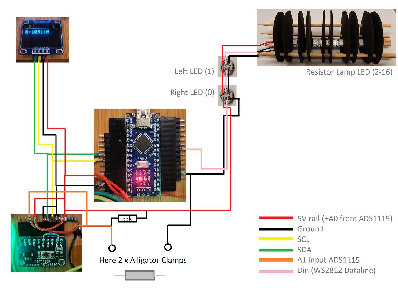


 Yann Guidon / YGDES
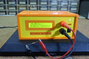
 mircemk
 Ted Yapo
 nqtronix
I am wondering if anyone has built this recentlly (march 2024)