 mircemk
The HPDL-1414 is a 16-segment LED display with four printable fields that is over twenty years old. It has a red GaAsP screen to which we can add the epithet "smart", because it is capable of printing alphanumeric characters on its fields. The screen is controlled by a CMOS integrated circuit embedded in a plastic housing.This circuit contains RAM, ASCI II decoder, multiplexer and LED drivers. Thanks to these features, no additional components are needed to connect this display to the microcontroller.
More displays can be connected in series, where for each subsequent one it is necessary to assign another GPIO to the WR pin, similar to the SPI interface.
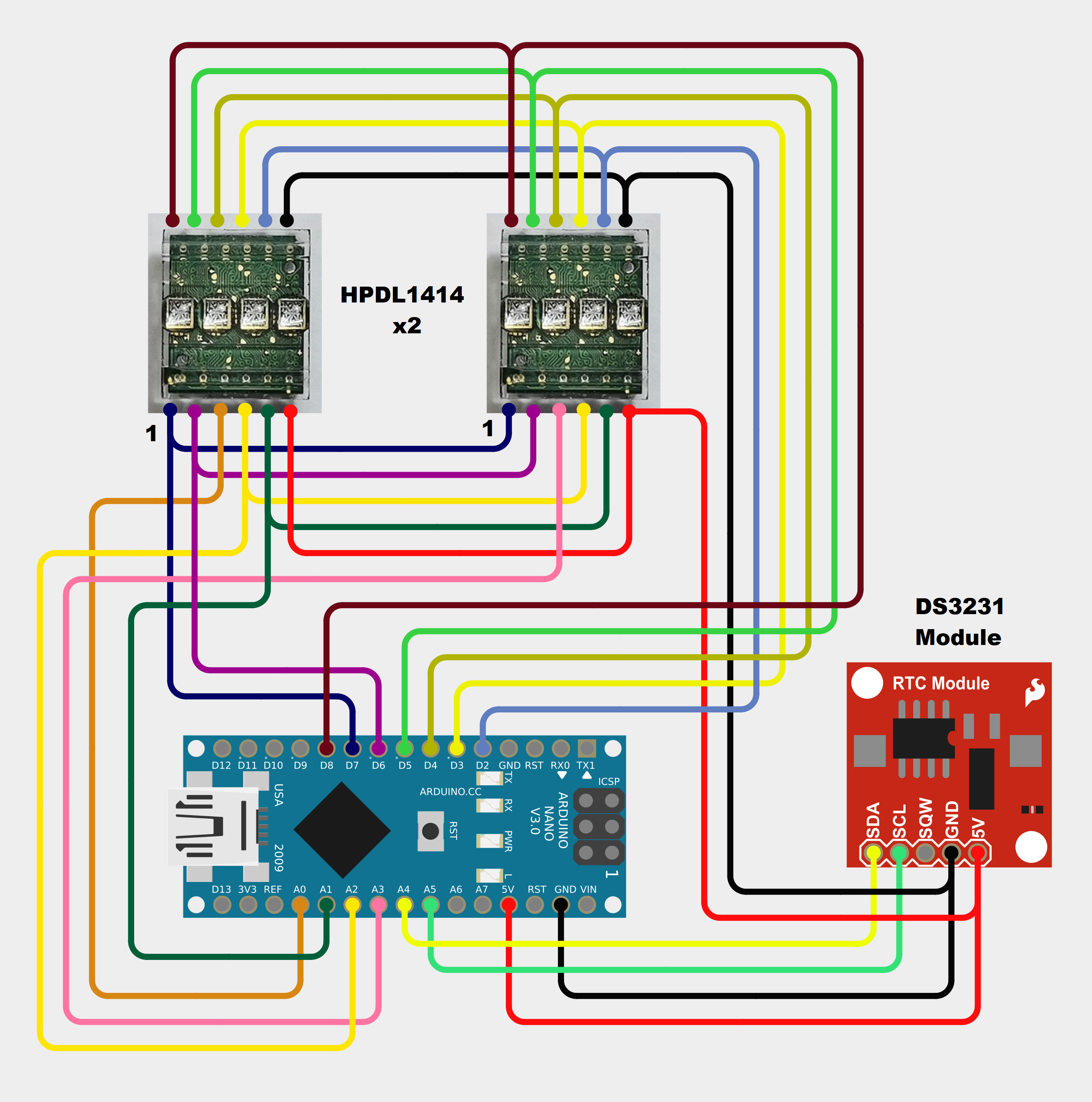
This time I will show you how to make an interesting mini Retro-look Clock with such a displays, as well as the way in which static and moving text can be written on it. For this purpose I wrote a super simple code, and a Schematic diagram.
The device is very simple to make and consists of several components:
- Arduino nano microcontroller
- 2 pcs. HPDL-1414 Led displays
- and DS3231 Realtime clock module
- These three buttons are not connected to the circuit at the moment, and in some of the following versions of the code, they are intended to be used for setting the time and possibly the alarm. If you want to make your own PCB for this project, or for any other electronic project, PCBway is a great choice for you. PCBway is one of the most experienced PCB manufacturing company in China in field of PCB prototype and fabrication. They have a large online community where you can find a Open Source projects, and you can also share your project there. From my personal experience I can tell you that on this community you can find many useful projects with alredy designed PCBs, from where you can place an order directly.

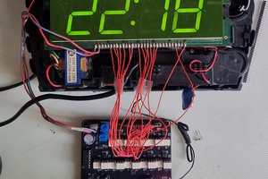
As I mentioned earlier, the link below provides separate codes for static text or moving text at the beginning before the correct time appears. When switching on, the moving text appears first, and then the correct time, in the form of hours, minutes and seconds. In front of the displays I put a darkened film for better visibility of the digits.
With the code itself we can set the exact time of the clock, which we need to enter in the lines:
rtc.adjust(DateTime(F(__DATE__),F(__TIME__)));
rtc.adjust(DateTime(2022, 8, 26, 23, 07, 0)); //Exact time on the moment of uploading
Then we need to upload the code once again with the same lines commented out
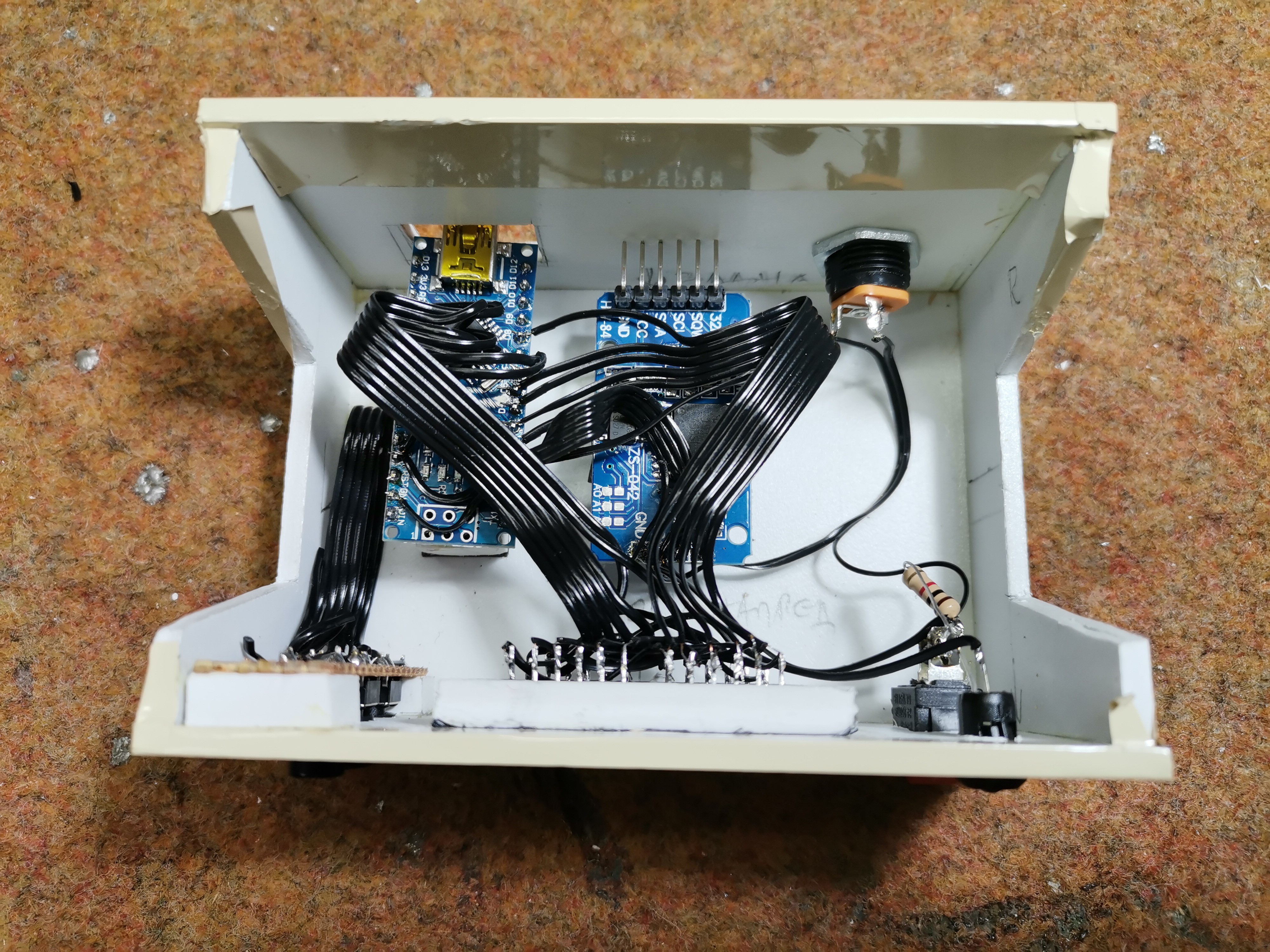
Finally, the device is mounted in a suitable box made of PVC plastic with thicknesses of 3mm and 5mm, and covered with self-adhesive colored wallpaper.
 zst123
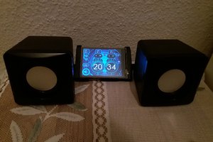
 Chris B
 jens.andree