 zakqwy
Introduction
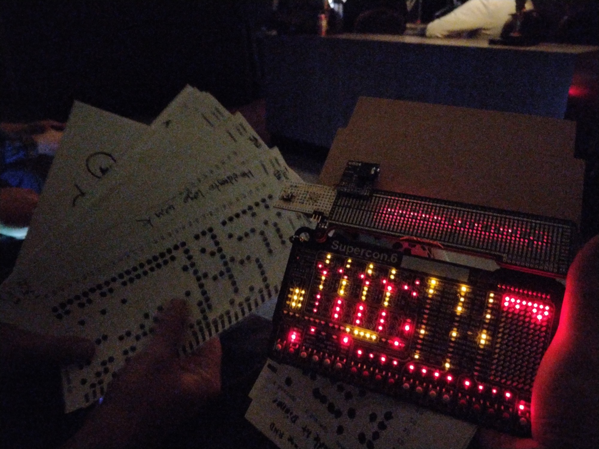
Above, the Card Reader (top right) attached to a stock Supercon 2022 Badge (bottom right), next to a stack of attendee-provided programs marked on custom sheets (left). Photo directly after presentation Sunday evening, showing Kenneth's successfully loaded 128-bit counter ("A Candlelit Dinner") still running. Note illuminated scan LEDs, forever awaiting their next program.
The Supercon 2022 Badge Card Reader is a transmissive optical input device designed to facilitate loading hand-marked paper programs onto a stock Supercon 2022 Badge. The Card Reader consists of two arrays of thirteen red LEDs on 0.3" (7.6 mm) centers, harvested from a donor badge, which face each other across a minimal gap set by several layers of cardboard shims and guides. One set of LEDs serve as a single receiver; they are wired in parallel, reverse-biased, and fed into a transimpedance amplifier with 1E6 gain. This useful if somewhat finicky technique can be traced back to Forrest Mims III's various experiments and published circuit diagrams on the subject. The other set of LEDs are Charlieplexed and scanned sequentially, illuminating one bit at a time in rapid succession. All of the LEDs are managed by a Pixelblaze Sensor Expansion Board, chosen for its convenience (as Ben is also known as ElectroMage, Creator of Pixelblaze, and thus had a few extras in his bag) and its 12 bit, 1 Msps ADC.
The printed programming cards store 32 12-bit hand-marked words, providing a 1:1 match to the Supercon 2022 Badge buttons in quantity, function, and physical spacing. Each line also includes a prefilled sync bar which is used to trigger the ADC reads for each row and to serve as an overall word counter for a given scan. In use, cards are fed into the top of the Card Reader and smoothly drawn through by hand. If the sync bar count is not 32 after a brief delay, an error LED flashes and the card must be re-scanned. If the count is correct, the word order is inverted (as the cards are inserted end-first) and added to a buffer. Once the last card is scanned, the badge is placed in UART programming mode, the Card Reader button is pressed (there is only one button, also harvested from a donor badge), and the program is transmitted via the Badge header connector to the waiting RX pin.
Build
We both showed up to Supercon on Friday morning. Soon after receiving our badges at SupplyFrame HQ we agreed to team up for some badge hackery. Ben suggested the idea for a punchcard reader which Zach enthusiastically supported. Early on, we felt that using as many commonly available components as possible was worthwhile (and neither of us had brought a pile of photodiodes), which led to stripping a few dozen red LEDs off Zach's badge using a hot air tool. We ran a quick test, reverse-biasing an LED with a few volts and running it through a 1 M resistor, and then checking the voltage across the resistor using a multimeter under a few conditions: ambient illumination, opaque coverage, paper, and Sharpie-marked paper. The latter two measurements differed by a few dozen millivolts, which seemed promising enough to pursue. We decided to match the button spacing and commenced soldering LEDs to our two supplied expansion prototyping boards:
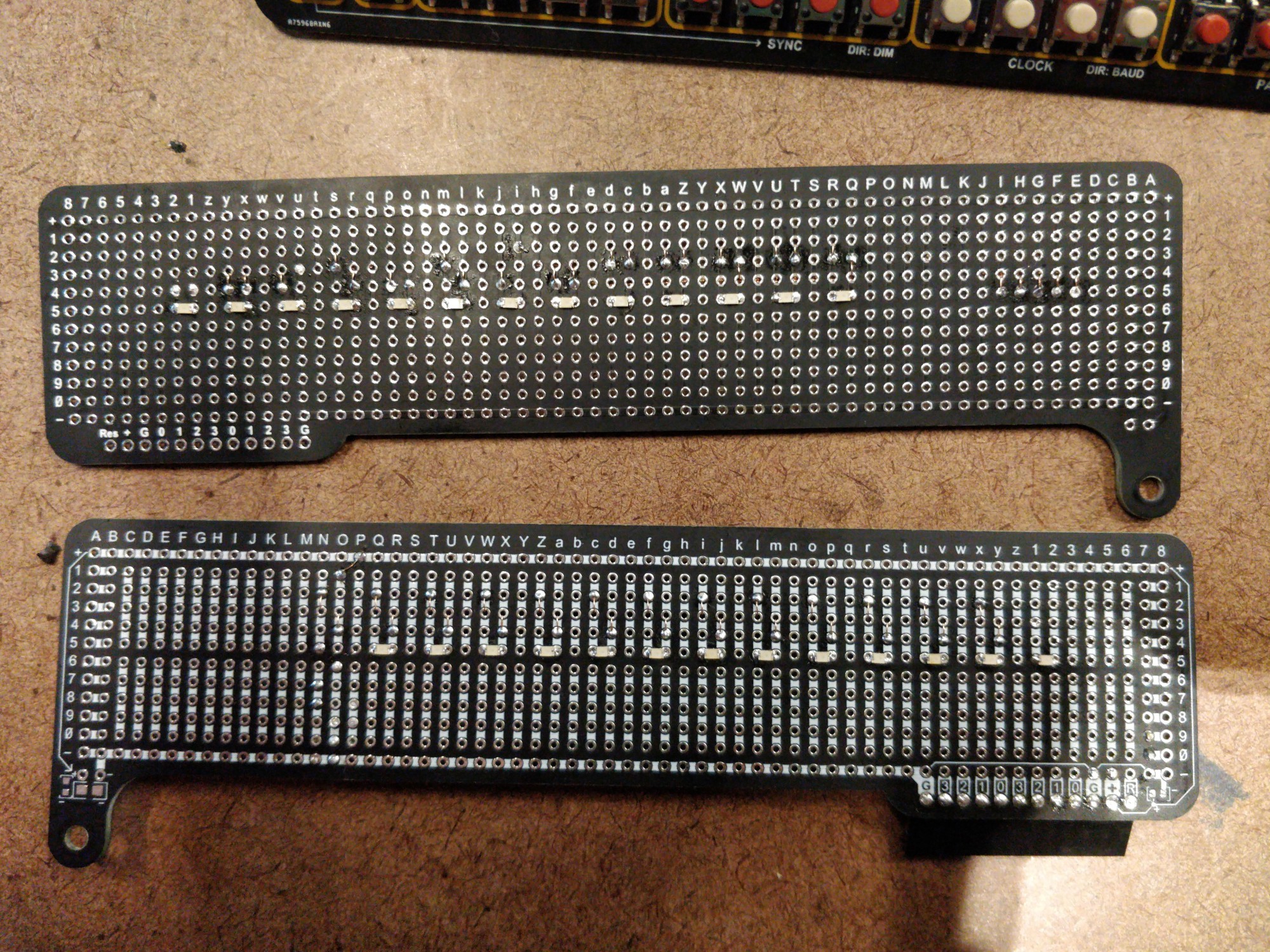
Above, bare illumination board (top) and sensor board (bottom).
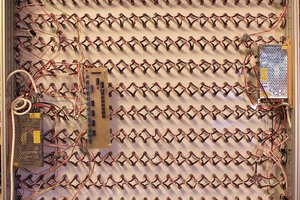
Point-to-point wiring is accomplished using our mutual favorite 34 AWG polyurethane-insulated magnet wire, which is relatively easy to thermally strip using a bit of flux and a well-tinned iron tip. In both cases, the bulk of the interconnect happens on the side opposite the LEDs; this was particularly important for the Charlieplex wiring, which overlaps a few times and would complicate adding guides and light shields down the road. After assembly, we tested the LEDs for continuity (and subsequently reflowed a number of sketchy magnet wire joints) and Charlieplexing logic:
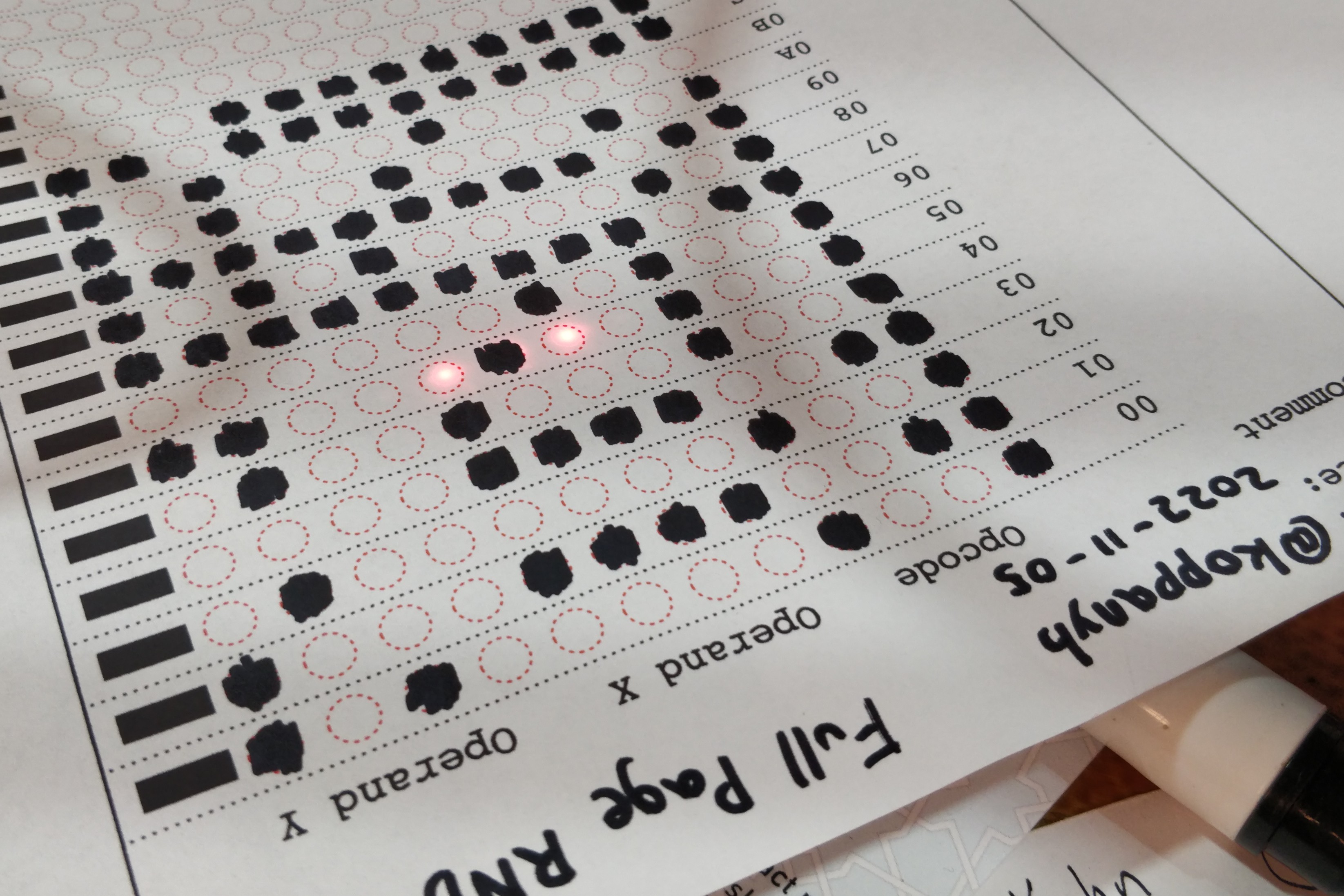
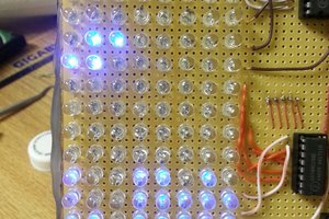
Above, early testing of the illumination board with a marked programming sheet. We...
Read more »


 Yann Guidon / YGDES
 hackaday
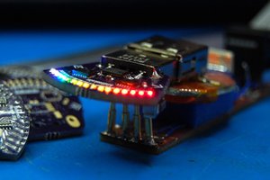
 Alex Bowen
Thanks for sharing all of the details so we can all learn from your project!