 Juan-Antonio Søren E.P.
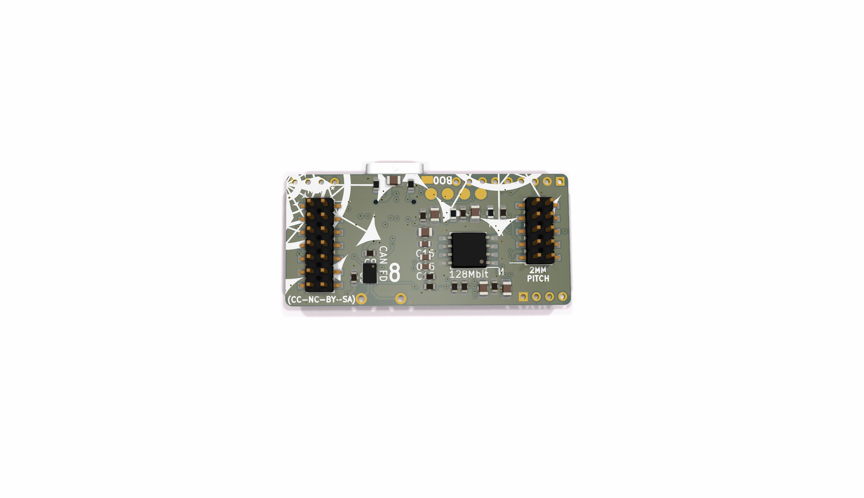
The MCU intended for testing is the SAME51 120Mhz MCU with FPU (Floating Point Unit). If powered and cooled optimally it can be overclocked to 200MHz. (Mind you that the MCU is modular, and could potentially have a higher clock). The SAME51 has a CAN FD interface.
The ADC does 1 million samples per secund, which is great for the currents sensors (MAX40056), since they have a 300 kHz bandwidth.
Let's extrapolate those numbers;
If our NEMA23 drivetrain moves the machine 2mm per rotation, in order to move 1400mm/min we would need to rotate the shaft 700 rpm.
700 rpm is 11.667 rotations per sec.
With a 300 kHz bandwidth, the MCU then has 25.71 kHz samples available per rotation, that is 71 samples per degree (when moving @1400mm/sek) or per 0.0055mm movement.
If we use the 200 steps or cogging-steps of the motor, we then get 128.5 current_samples per step.
Regarding MCU clock;
With a 120Mhz frequency we can calculate the Clock-cycle´s available.
120.000.000 / 11.667 rps / 200steps = 51.427 clock cycles per electrical revolution @1400mm/min
PWM Frequency VS PWM resolution
When setting the PWM frequency, the clock used is the main MCU clock, in this case 120MHz. Each PWM cycle counts the clock ticks up to set PWM resolution. If dual slope counting is used, the counter count from 0 to max and back to 0.
To set a 50 kHz PWM frequency with a 120MHz clock (120.000.000 per secund) one will have a resolution of 2400 clock ticks per PWM cycle.
Having a 50kHz PWM frequency will make the MOSFET fire 6 times slower than available ADC samples. So 50kHz / 11.667 rps / 200steps = 21,43 PWM cycles per electrical revolution @1400mm/sek.
This means we can oversample to 14bit analog resolution current samples.


 Simon Trendel
 Benjamin Prescher
 Sillhouette
Awesome work! Looking forward to seeing how this progresses. I have been torn between closed loop stepper drivers at 24v and 48v standalone drivers for my nema 23 steppers. A combination of the two would be great.