 Andy Geppert
Project Goals:
- Interactive and fun to use.
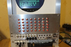
- Fit with the 4-bit computer era theme.
- Made from parts available in my laboratory.
I found the dialer and the edge connector/card, some OLD protoboard, and some 555s. After I pulled those items together, I designed a couple of parts to hold the bits together and printed them. The wiring is simple: a common wire to ground, and the ONHOOK and PULSE signals to a pair of inputs on the Badge. Conveniently, the badge input lines already have pull-ups installed. I used an oscilloscope to look at the pulses. They were surprisingly clean so I skipped hardware debounce and figured we'd be able to find a clock speed that would work reliably with the code to provide "natural debounce." All of the hardware was completed prior to Supercon.
The logic is simple. Wait for the ONHOOK signal to drop (High to Low transition), then count dialer pulses (Low to High transitions). I created a flow chart Saturday night at Supercon, with the intent to hand code it Sunday... but time was slipping away, and teamwork was in order! @Michael Welling happily obliged, and he took on the bulk of the translation from flowchart to assembly language. While I was noodling on the flow chart, he had gotten the assembler and serial upload working which made development much faster (duh!. You'll see numbers in the flow chart (100, 200, 300...) and those correspond to the areas of program memory where I was going to start coding each block by hand.
To make debugging easy, we kept everything on the first page of Data Memory, including displaying the digit that was dialed. Register usage follows:
R0 = Used for comparisons - this is a special register by design of the 4-bit instruction set
R1 = Heart beat (on at the top of the flow chart, off briefly at the bottom before going back to the top)
R2 = Rotary Count Total (counts up in binary as the pulses are accumulated in a single dial stroke)
R3 = Rotary Count Input previous state (used to find edge transition)
R4 = Onhook Input previous state (used to find edge transition)
R5-9 = Display rows
RA = Out (not used)
RB = In (bit 0 is pulser, bit 1 is on hook)
The display routine sequences through each digit, starting with 1. The first digit is displayed, and then the Rotary Count Total is decremented until it is zero... which means it's time to stop drawing digits. The last digit drawn will be the correct digit corresponding to the total that was initially in the Rotary Count Total register. Yes, it's a hack, but it works!
After some experimenting with clock speed, we found 1000 Hz and 500 Hz worked reliably, and we are not seeing any extra or missed counts.
Thanks for the code skilz @Michael Welling! And thanks to my table mates for so willingly answering questions and allowing me to interrupt their own projects. Especially @koppanyh who is an incredible inspiration with HAND WRITTEN TERTRIS!
3D Print files design in OnShape:


 dave
dave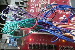
 zpekic
 Yann Guidon / YGDES
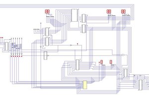
Hmmmm, I recall having a rotary dial in my junk shed. Now I see yet another project in the future....