 AirCruiser
Contents
- Principle
- Perfboard Tests
- The First Flight
- Disassembling the DJI Battery
- SBCB <> Breakout Perfboard Connection
- No Magic Without the Appropriate Software
Principle
I haven't found a practical way to reproduce/decrypt the authentication between the smart battery controller board and the drone. Therefore, I decided to scrap my plan to fully replace the control board. My new attempt was to build a board that communicates with the drone most of the time. However, when the drone requests authentication, the communication will be forwarded to the original smart battery control board (SBCB). After authentication has been successfully completed, the modboard should handle further communication. But as it turns out, only one command must be manipulated for my approach to work. Therefore, I changed my strategy, as shown in the sketch below.
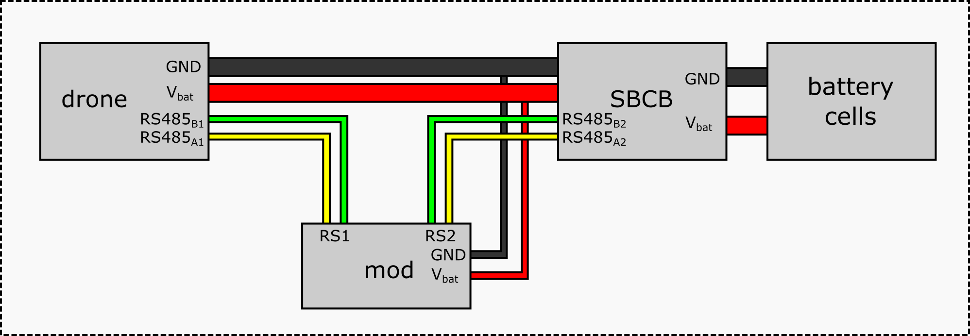
The new approach was to put my mod between the original SBCB and the drone. My mod should parse all DUML messages and forward them both ways. The data must be modified before forwarding only when the GetPushDynamicData command (CMDset 13, CMDID 2) is sent from the battery to the drone. So you can say it is a kind of "man-in-the-middle attack". Since my mod allows batteries from other manufacturers to be used instead of the original DJI batteries, the name Battery Breakout Board is probably appropriate.
Perfboard Tests
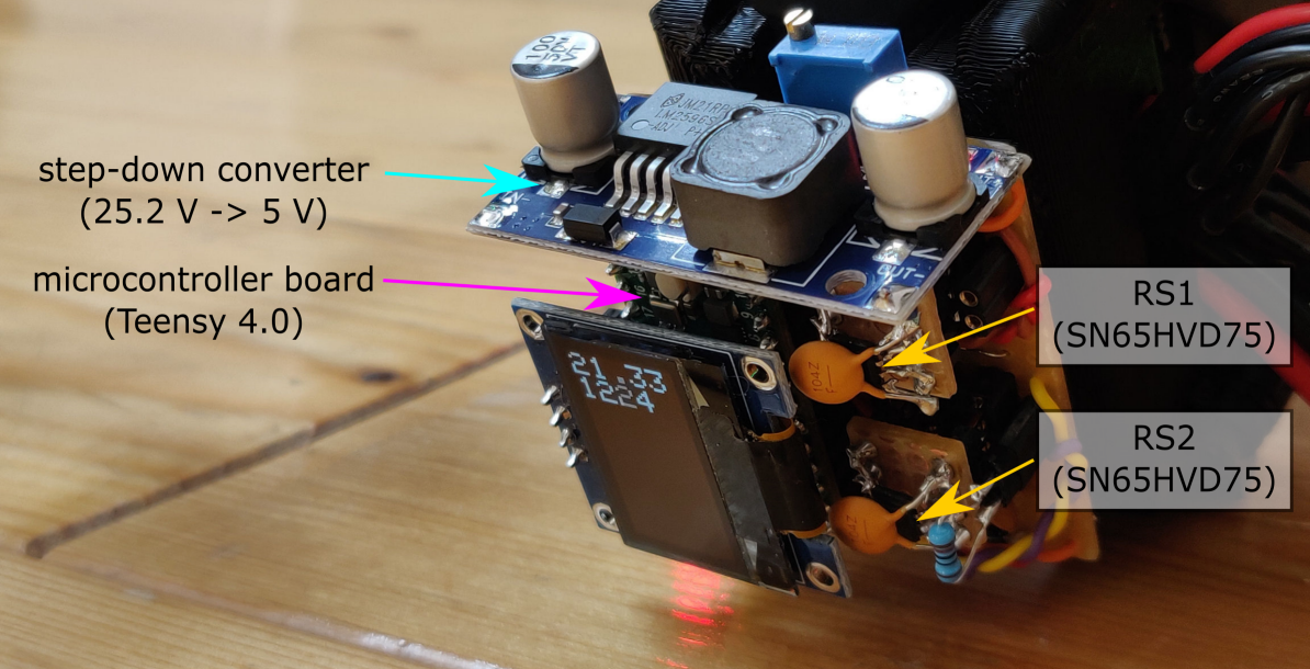
The images below shows the electronic schematic of the first perfboard test and a picture of it. A simple buck converter was used to step down the input voltage from the battery (19.2V - 25.2V) to 5V to power a Teensy 4.0 development board. This board uses 3.3V logic like the SBCB, so my first thought was to adjust the buck converter to 3.3V output voltage. But it's not recommended to drive the Teensy directly with 3.3V, so I didn't do it ;)
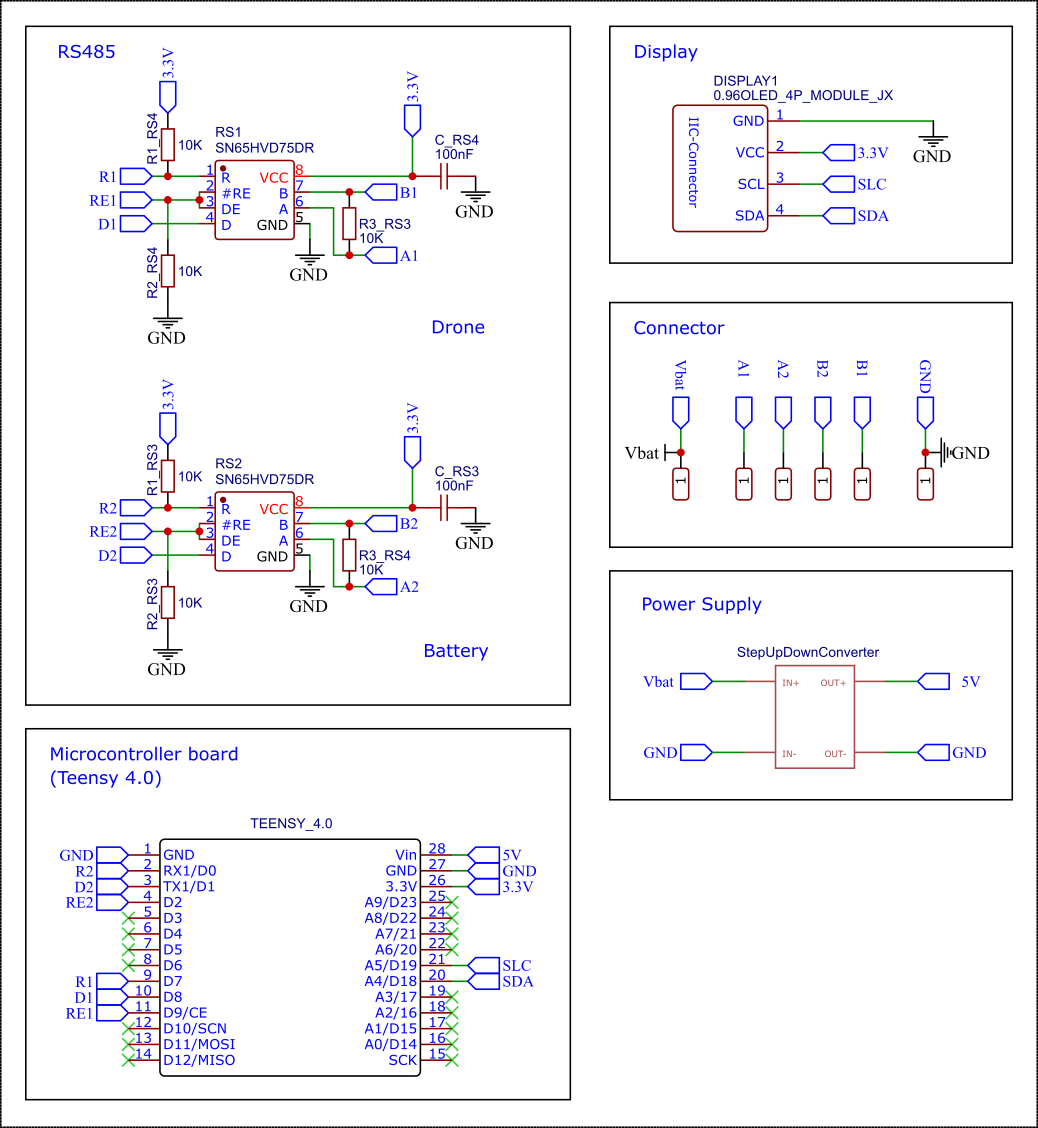
I chose to use the same RS485 communication ICs that I found on the SBCB to ensure that these chips could not be the source of misbehavior. The only problem was that these were SMD chips, which cannot be easily hand-soldered onto a perfboard. But with a little practice and patience I managed to do it. I used the reference design suggested in the Texas Instruments IC datasheet. The data sheet recommends the use of termination resistors to eliminate line reflections. I tested some values and found 10 kOhm to be a good choice. But there was a large range without any noticeable problems.
The digital inputs and outputs of the two SN65HVD75 ICs were connected to UART1 and UART2 of the Teensy 4 development board. The active pins of the driver and receiver of the ICs are connected (for each IC). Therefore, the SN65HVD75 can send data when the pins are set HIGH (3.3V) and receive data when they are set LOW (GND).
It must be mentioned that with this configuration, serial ports 1 and 2 must be configured to send and receive inverted signals.
Serial1.begin(115200, SERIAL_8N1_RXINV_TXINV);
Serial2.begin(115200, SERIAL_8N1_RXINV_TXINV);
As you can see the additional parameters are 8 data bits, 1 stop bit, no parity bit and 115200 bps.
The First Flight
As you can guess from the picture and video, the perfboard version was a mess. It was very bulky and it took a lot of work and effort to solder it. Unexpectedly, however, it worked perfectly.
Disassembling the DJI Battery
I suggest reading the battery disassembly section of the first part of this project for more information: https://hackaday.io/project/184677-dji-fpv-battery-breakout-mod-1-first-tests/details
Carefully open the original DJI battery. There are two small screws that you will need to remove. In addition to four clips, there is some sort of double-sided tape that holds the battery cover in place. The LiPo cells are also stuck to the floor with double-sided adhesive tape. It's a little difficult to remove, but possible. Be careful not to damage the LiPo cells or the SBCB when opening the case.
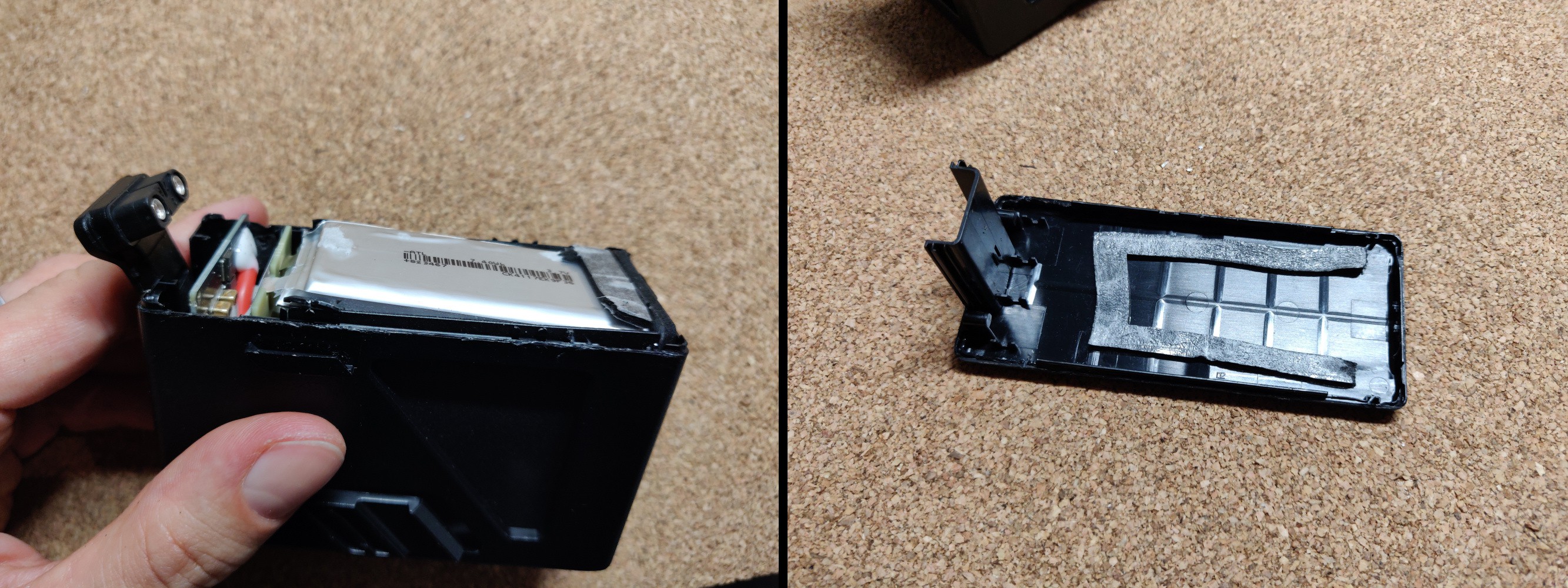
After you have released the cells, you can pull them out of the case together with the SBCB. I can't stress enough that you have to handle the LiPos with care! Even a small short circuit can cause explosions and fire! Always stay focused and clear.
Next to the two thick power cables and the thin balancing wires, there is a temperature sensor glued between the LiPo cells. Detach it carefully and take care not to damage the wires.
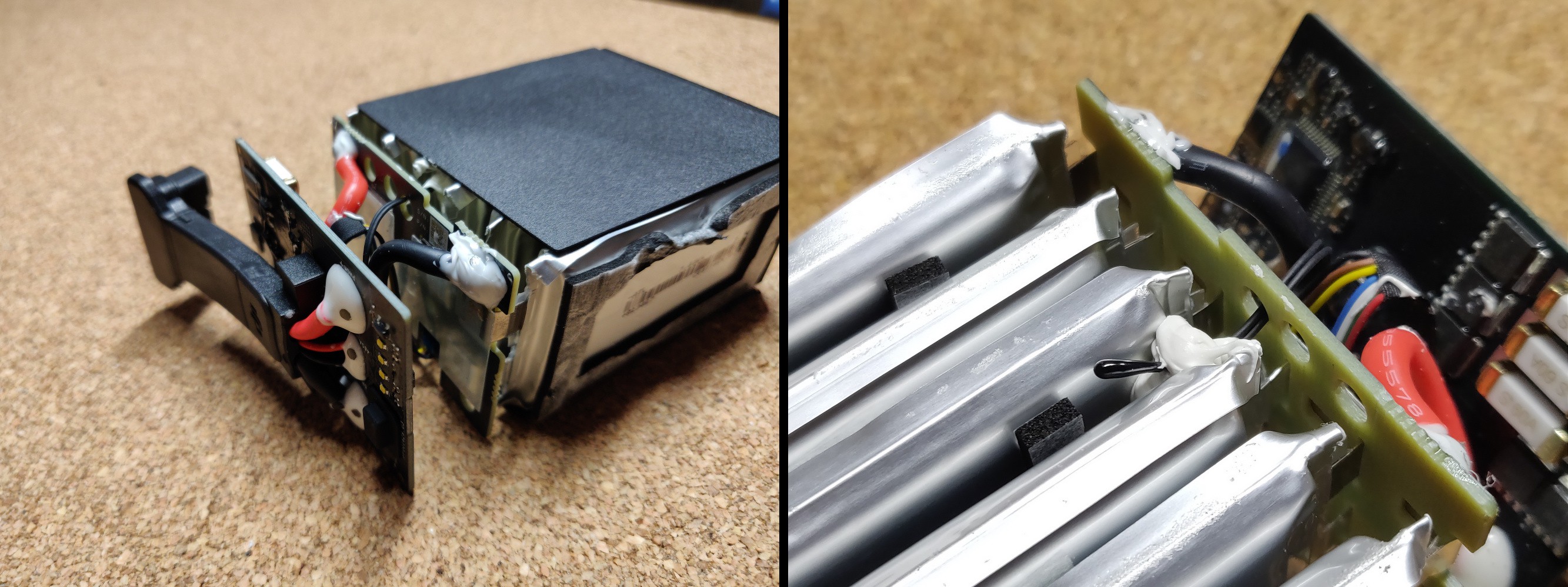
Now you need to disconnect the SBCB from the LiPo cells. I recommend cutting the wires with a sharp side cutter. It is important to cut all the wires separately. Otherwise you will short one or more cells!
Make sure that the wires do not touch each other after cutting.
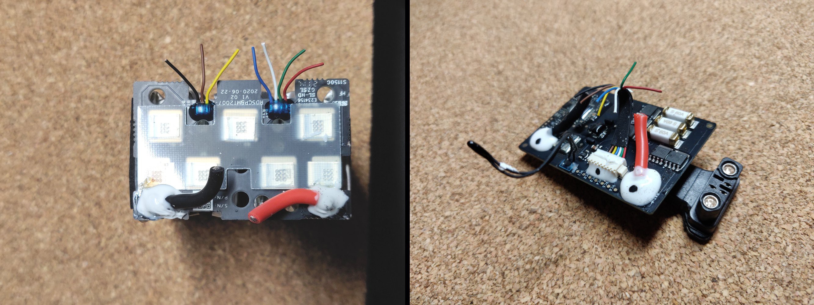
You need to solder the power cables on the back of the SBCB to a XT60 (male) connector and the balance wire (thin black = GND, brown = 3.7 V, yellow = 7.4 V, blue = 11.1 V, white = 14.8 V, green = 18.5 V, red = 22.2 V) to a JST-XH connector. It is REALLY important to work concentrated and correctly. Any wire soldered incorrectly could destroy the board and the drone.
Do the same for the LiPo cells, but use female connectors instead of male.
The solder pads of the power cables on the SBCB and the LiPo board are covered with some kind of glue. It is possible (but a bit time consuming) to remove the glue, unsolder the short cables from the board and solder new cables to the pads. Because of the thick wires and large solder joints, your soldering iron must have at least 50 Watts of power to do this. But that's also true if you want to solder your own battery packs. So you should have such one ;)
When (de)soldering the power cables, you should keep an eye on the temperature of the PCBs. The heat is well conducted by the PCBs and could damage other components if they get too hot.
Instead, you could also solder new cables with XT60 connectors to the remaining short wires. This is easier and faster, but a rather ugly solution.
SBCB <> Breakout Perfboard Connection
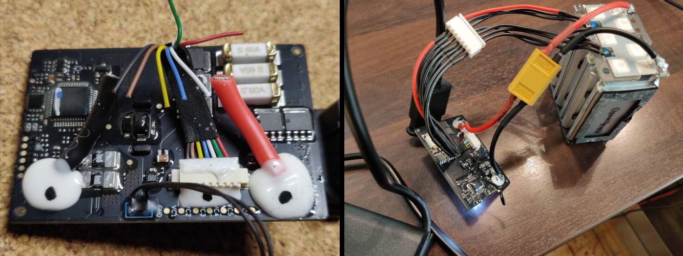
As shown in the first sketch, the power cables between the drone and SBCB can be used to power the breakout board. Additionally, the RS485 data connection must be separated and split into two channels. The cables coming from the drone must be connected to RS1 and the cables going to the SBCB must be connected to RS2. Below are some images that give an idea of what to do.
First I removed the glue from the solder joints with a sharp knife (scalpel) and a wooden sticks (this prevents damage to the circuit board if you slip off). The result you can see at the pictures below:
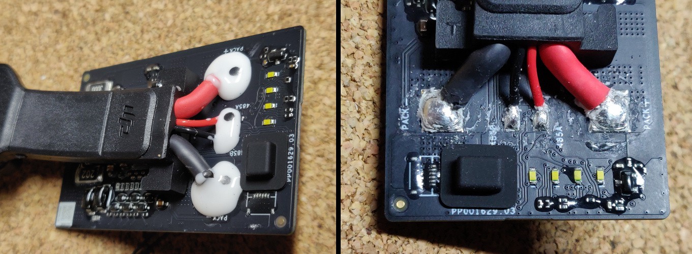
Then I soldered female headers to the solder pads to allow a plug connection to the breakout perfboard.
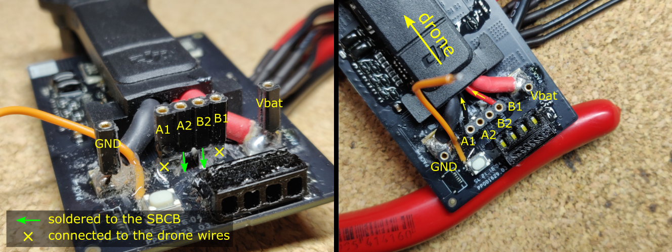
It is important to note that only the connectors A2 and B2 are soldered to the solder pads on the SBCB (the two in the middle of the top right image). The A1 and B1 connectors are just soldered to the thin black and red wires that go to the drone!
But of course it doesn't have to be a plug-in connection. The cables can also be soldered directly to the breakout board. After soldering the connection headers I used some epoxy glue to isolate and stabilize the solder spots and wires.
The orange wire in the pictures above is connected to the SBCB's power button on one side. The second side gets connected to a button on the perfboard so that the battery can be powered on with the perfboard in front of the original board.
No Magic Without the Appropriate Software
More coming soon!