 charliex
Got back from CES all ready to mount the new as yet to be tested motor.
First the intro video... yes more upbeat music from googles expansive library of music.
head spacer ready to mount


like so

then the other side of the spacer connects to here.

underneath on the head where the bolts come in there was some flashing that made it hard to insert the long bolt, so i ground it away.


mounted it to the head and bolted it down so we can centre punch holes for the two m4 bolts we've added .

using a tap guide and drilling out the cast for the new holes. cast iron is messy to work with, its a good idea to keep cleaning it up and keep it away from any moving parts, motors, ways etc.
removing the Z column bearing/motor mount


mounted the head onto the spacer

bolted it up and its done for now, this is a temp piece while we decide if we want to go to a steel spacer. we need this to fit the motor, though it hurts our Y travel til we extend the bed.

The side rails we did last week.
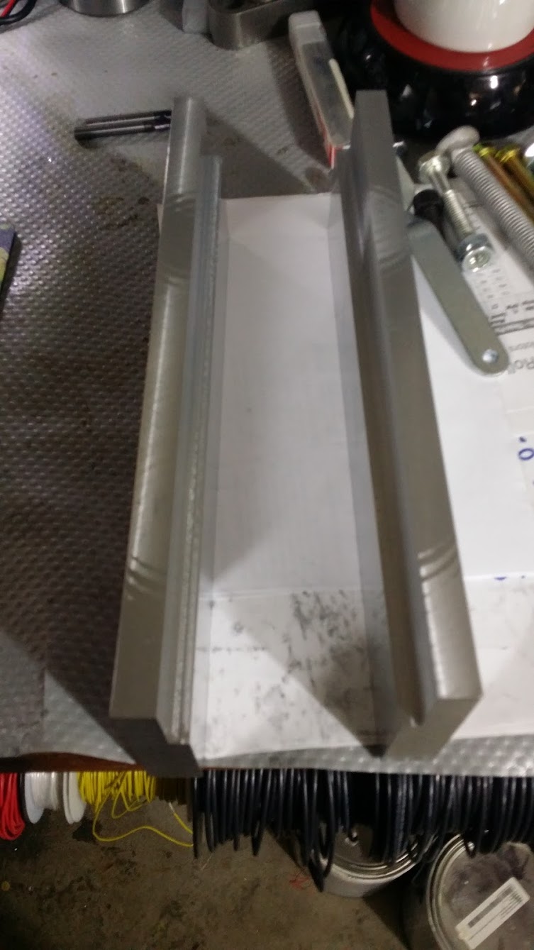
these need to be pocket out for clearance for the pan head bolts that are on the motor plate.
the motors been arcing quite badly in the last few weeks, we're hoping it lasts for these few cuts.
cutting down some bolts to fit the Head extension
the bolts needs to have a T shape so they wont spin in the head mount. so grinder again.
test mount, the clearance at the back is off , it ends up looking like a green latern symbol , the more we see the motor on here, the less it seems oversized.

we have to drill and tap holes in the side of the cast to mount the plates.


marking out the area to remove from the back to stop the Z motor square hitting it. the white is a marker that doesn't get easily removed as sharpie.
motor isn't that big!


next is to punch , drill and tap the holes in the cast


also added on the two blocks per side, the motor plate attaches to these.
more tapping
and its mounted


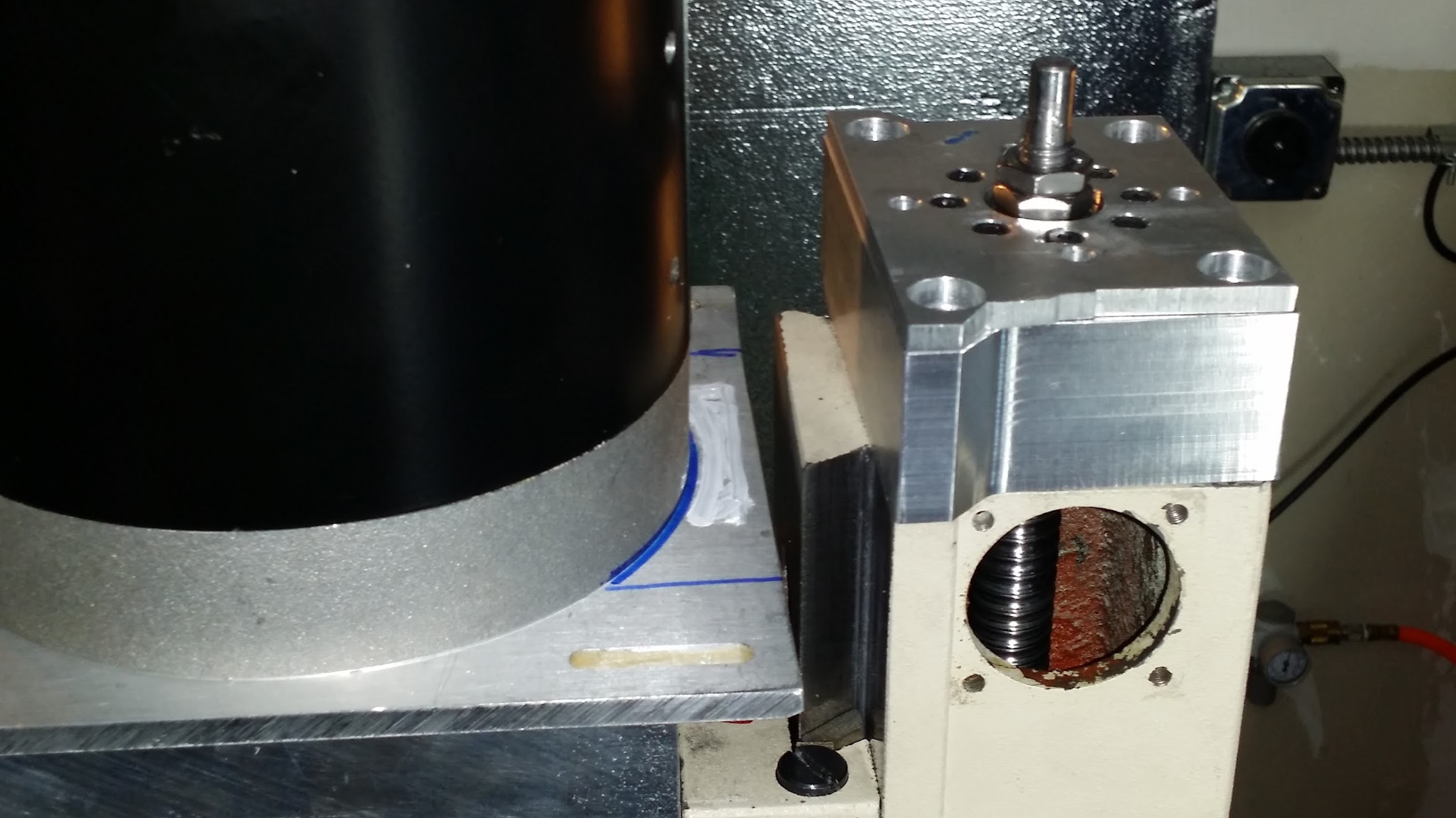
we've been having some issues with the tormach TTS pulling down during cutting, you can see the results of that on the back left of the plate. A PDF on tormach's website says its because its not clean, so we'll try that. http://www.tormach.com/uploads/163/TD31090_ToolHolding-pdf.html
mounted the motor plate marking the holes to drill in the top. M6's again


after its bolted up i wanted to test the clearance. hand drill works great.
the top of the motor fan cover would have clipped it, so chopped off the edge of the aluminium channel.

all mounted, drilled and tapped. time to see if the stepper can move the all the new weight.
we stopped at 100IPM not bad, no point going faster.
time to wire the motor


we're using 240V so tie both sides together l1/l2/l3, connect all the INS (t4/t5/t6) to themselves and insulate(thats what INS means)
the motor plate shows the wiring. we then used wire nuts + extension coord + ground to run to the VFD.

running the 220V, i used a dryer cable which is massively overkill, ended up wire nuts + smaller gauge wire to feed into the VFD

knotty!

i'd added the breaker box and outlet previously, so just need to be plugged in, again massive overkill.

and fire up the motor! (now at this point there is something we should have checked and didn't) you might spot it..
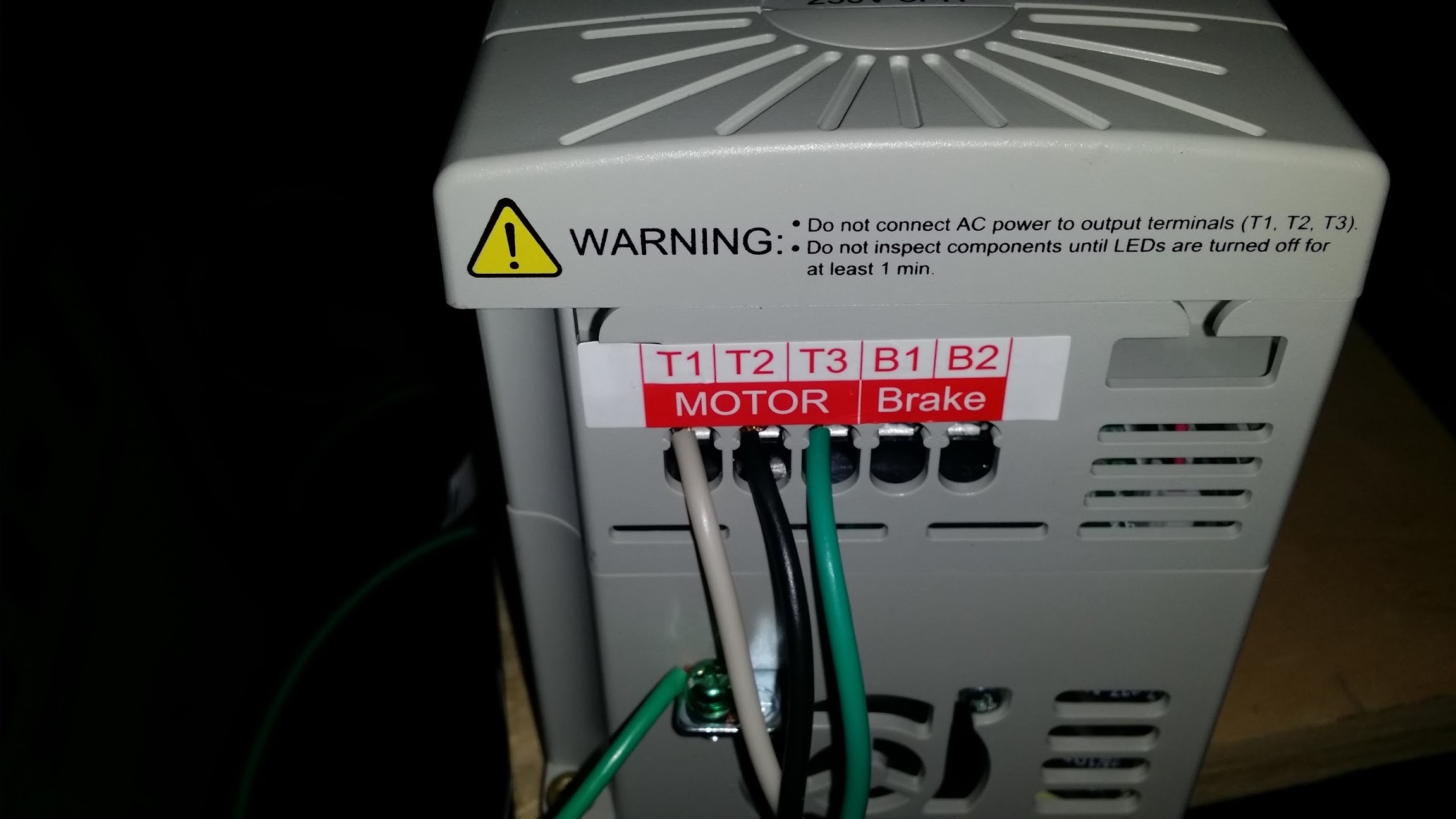
VFD wiring, dead simple two hots + ground to the 220V outlet, and then three phases to the motor + ground to the machine. the order is important.

This is a GS2 which isn't a sensorless vector, which we didn't realise, it was the one recommended by Automation Direct, and its perfectly fine however we wanted the sensorless +auto tune etc, so i emailed the people at AD and say we just wired it up , did a couple of test cuts/runs and realised, so can we upgrade to the GS3. To be honest i was expecting them to tell me where to go and was preparing to say to the wife, not only do we want to go to a bigger motor but we might have to buy a second VFD since the first is potentially the wrong one.
However AD emailed me back in the morning with a return slip and said just pay for the GS3-22PO , and we'll refund after getting the GS2 back. They've always been super helpful but i'm real happy about this, luckily for once i saved the packaging and box ( since AD included a note saying so) normally i'm usually we'll figure out another use for it.
So they're sending me out a GS3 tonight and we'll wire it up this weekend, next is an inverter duty motor upgrade, probably 1.5HP is the sweet spot... thank you Automation Direct.. The advice they gave me for the GS2+1HP motor is perfectly fine, we just want the fancy features, it is about $40 more.
Now there is a couple of videos missing of the first cut, i hope its on my gopro since we decided lets put 1HP into the CAM software and see what happens, 28IPM for a .250" end mill with 0.76" DOC is what happened, so we set it up , put on some test material and did some facing with a face mill, no low speed torque, doesn't cut for toffee. oh well (and this is where we start discussing the sensorless GS3)
mounted up the .250" bit and tried the new hole, nope , doesn't cut the material, horrible noises and the motor stalls.. ok half the speed, try again, same thing gets about 1mm into the aluminium, damn .. ok half the speed again, this time regen the CAM , using the math at .37HP ends up at 11 IPM which is about where we cut at with the old motor.... nope still won't cut, stalls noisy etc... motor is about 3 times bigger, and less capable ? WTFMATE?
I start looking up new inverter duty motors since we've got it it in our head about that constant torque ratio, since we're running about 40% of the motors frequency, we're convincing ourselves somethings wrong in the setup.
I email A.D. about swapping to a GS3. I find a motor they're all 145TC146 mounts so start CADing, but this time its about 00:30am on Monday morning and we think ok lets pack it in and head home, on the way out of the door , bag in hand, mmca says haha did we check the spindle is spinning the right way, we look and laugh of course it must be.. .then we start to get that dawning moment, surely not... quick switch it all back on and test,..... and yes the motor is spinning the WRONG way, so we're basically end-milling by scraping the material..
Ok, swap two of the motor phase wires (T2/T1), bring up the CAM at 11IPM, cuts like butter... 22IPM, same, 28IPM cutting but its chattering, pretty good really since we didn't expect the machine to handle 28IPM. we notice the TTS is slipping again so abort the cut. But turns out the 1HP general purpose motor is doing just fine so far....
i'll dig up the scrapping video when i get home. Also note the T1 and T2 are swapped on the motor connecting on the VFD in the second picture above. that is correct T2/T1/T3 from the motor.
til next week!. And thanks again Paula from Automation Direct.
Discussions
Become a Hackaday.io Member
Create an account to leave a comment. Already have an account? Log In.