 ElectronicABC
GERBER PCB :
https://mega.nz/file/WFgDUTCL#LLngIZF73Lf2cGm9vP-BvET51hIcJsxVjtlC5bAV13I
WS2811 DATASHEET:
https://mega.nz/file/XJhQ3SRI#Ot3Y0BEJNv_dxzCAS-EkjkFatpmuN6S8utP8Nev_rrU
LIBRARY NEOPIXEL ARDUINO:
https://mega.nz/file/qI52BBJI#w4BjJnnlkzSJ7FEiPVEF__tyNKgighTykt7Jp3K5Bks
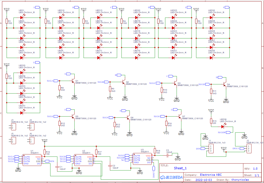
SCHEMATIC DIAGRAM
As with any project, we will first see the schematic diagram to be able to analyze it and understand its operation.
FUNCTIONING
This 7-segment display module can be used with any microcontroller or Arduino whose input is 5V - DIN - GND and its output is 5V - DOUT - GND
DIN is the serial data input that our Arduino will send to control these displays with only 1 pin we can control more than 4 display modules and this module in turn allows to expand more display in serial mode by connecting the DOUT with the DIN.
For this project we have used the W2811 chip that controls the intelligent RGB strips but now instead of controlling the RGB we will control the segments
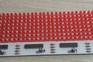
My design has 7 segments, that is, from A to G and the point.
WS2811

WS2811 - Driver for RGB LEDs.
3-channel LED driver, its internal includes intelligent digital port data input circuit and signal reconfiguration amplification circuit.
Technical characteristics:
• Power supply voltage: 6V - 7V.
• Operating temperature: -40C° +85C°.
• Output voltage: 12V.
• Built-in 24V voltage regulator tube, just add a resistor to IC VDD pin when voltage is below 24V.
• The gray levels of each pixel of 256 levels, and the refresh rate reaches to 2KHz / s.
• Send data at speeds of 800 Kbps.
ARDUINO TEST CODE COUNT OF ( 0-9 )
#include <Adafruit_NeoPixel.h>    // importa libreria

// Primer parametro = cantidad de pixeles en la tira
// Segundo parametro = pin de conexion a Arduino
// Tercer parametro:
//   NEO_KHZ800  800 KHz velocidad de datos (WS2812 y nuevos)
//   NEO_KHZ400  400 KHz velocidad de datos (WS2811 y mas antiguos)
//   NEO_GRB     flujo de datos en orden GRB (WS2812 y nuevos)
//   NEO_RGB     flujo de datos en orden RGB (versiones mas antiguas)

Adafruit_NeoPixel tira = Adafruit_NeoPixel(3, 2, NEO_RGB + NEO_KHZ800); // creacion de objeto "tira"
// con una cantidad de 8 pixeles, sobre pin 2 de Arduino y configurado para WS2812

void setup(){
  tira.begin();       // inicializacion de la tira
  tira.show();        // muestra datos en pixel
}

void loop(){
  tira.setBrightness(17);               // brillo global para toda la tira
  //for(int i = 0; i < 3; i++){   // bucle para recorrer posiciones 0 a 7
    // cada pixel en color azul (posicion,R,G,B)
    tira.setPixelColor(0, 255, 255, 255);
    tira.setPixelColor(1, 255, 255, 255);
    tira.setPixelColor(2, 0, 0, 0);
    tira.show();      // muestra datos en pixel
    delay(1000);
    tira.setPixelColor(0, 0, 255, 255);
    tira.setPixelColor(1, 0, 0, 0);
    tira.setPixelColor(2, 0, 0, 0);
    tira.show();      // muestra datos en pixel
    delay(1000);
    tira.setPixelColor(0, 255, 255, 0);
    tira.setPixelColor(1, 255, 255, 0);
    tira.setPixelColor(2, 255, 0, 0);
    tira.show();      // muestra datos en pixel
    delay(1000);
    tira.setPixelColor(0, 255, 255, 255);
    tira.setPixelColor(1, 255, 0, 0);
    tira.setPixelColor(2, 255, 0, 0);
    tira.show();      // muestra datos en pixel
    delay(1000);
    tira.setPixelColor(0, 0, 255, 255);
    tira.setPixelColor(1, 0, 0, 255...
Read more »
 ElectroBoy