Home automation or domotics is building automation for a home, called a smart home or smart house. A home automation system will monitor and/or control home attributes such as lighting, climate, entertainment systems, and appliances. It may also include home security such as access control and alarm systems. When connected with the Internet, home devices are an important constituent of the Internet of Things ("IoT").
A home automation system typically connects controlled devices to a central smart home hub (sometimes called a "gateway"). The user interface for control of the system uses either wall-mounted terminals, tablet or desktop computers, a mobile phone application, or a Web interface that may also be accessible off-site through the Internet.
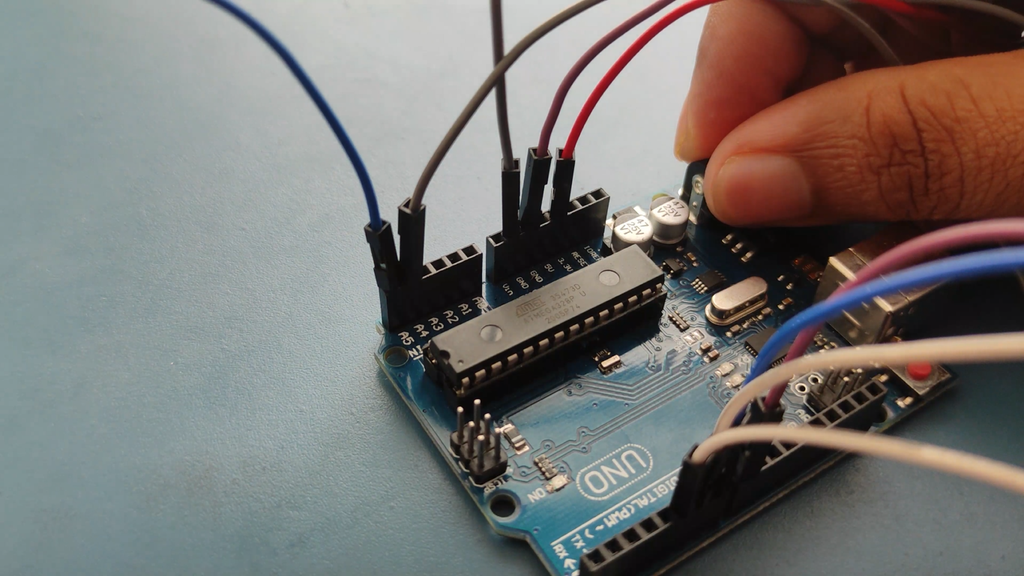
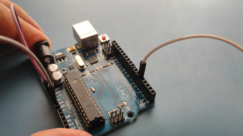
- Arduino UNO
- 10 KΩ Resistor
- 20 KΩ Resistor
- 1 KΩ Resistor X 4
- 2N2222 NPN Transistor X 4
- 1N4007 Diode X 4
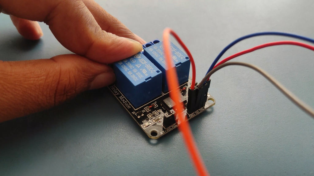
- 12 V Relay X 4
- Prototyping board (Bread board)
- Connecting wires
- 12 V Power supply
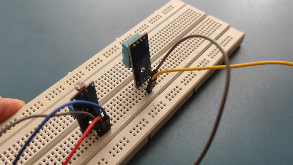
- DHT22
- LCD Display
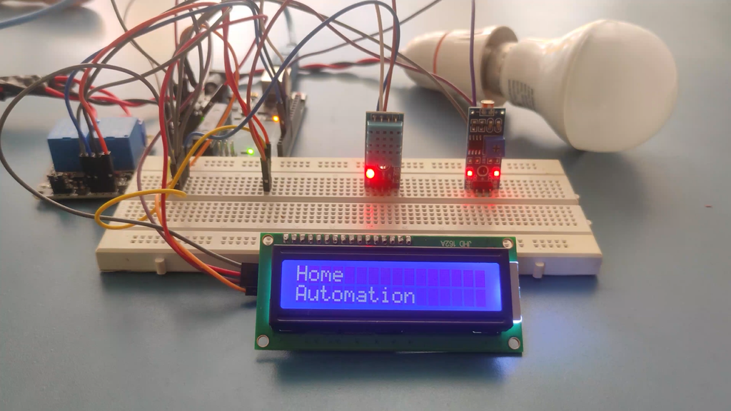
The circuit design of Home Automation based on Arduino and Bluetooth is very simple and is explained below.
The Bluetooth module has 4 – pins: VCC, TX, RX and GND. VCC and GND are connected to 5V and ground from Arduino UNO. The Bluetooth module works on 3.3V and it has an on board 5V to 3.3V regulator.
The TX and RX pins of the Bluetooth module must be connected to RX and TX pins of the Arduino. In Arduino UNO, we are defining pins 2 and 4 as RX and TX using software. Hence, TX of Bluetooth is connected to pin 4 of Arduino.
But when connecting RX of Bluetooth to TX of Arduino (or any microcontroller as a matter of fact), we need to be careful as the pin can tolerate only 3.3V. But the voltage from TX or Arduino will be 5V.
So, a voltage divider network consisting of 10K and 20K resistors are used to reduce the voltage to 3.3V approximately.
A resistor divider because it divides down the input voltage. We obtain the 3.3V level signal from the intersection of these two resistors.
The equation for a divided down voltage is Vout = [2.2k/(2.2k + 1k)]*5V = (2.2k/3.2k)*5V = 3.46V, which is close enough to 3.3V to prevent any damage to the HC-05.
This crude solution should never be used with a high-speed signal because the resistors form a low-pass RC filter with any parasitic capacitance on the connection.
As you can see the circuit is very simple and does not need many components to build. Let's start our explanation with the ESP8266-01 Wi-Fi module. You can also check out the video at the bottom of the page for a more detailed project explanation. To program the module, you need to first flash the firmware on the ESP8266 module and you also need to flash the firmware on the PIC12F675 module before doing anything.
The code section for this project will be divided into three sections because we are using two microcontrollers in our schematic, first one is an ESP8266 microcontroller and the second is a PIC microcontroller as you can see from the schematic. So the code for those two microcontrollers will be different and there will be another section where we will explain all the details about the webpage section.
Understanding the code for Atmel Microcontroller:
In this section, we will explain how the code for the PIC microcontroller works. We start our code by including all the required libraries in which some are builtin libraries and some are custom libraries. We also define all the required variables.
#include <xc.h>#include "config.h"#include "pinmanager.h"#include "peripherals.h"unsigned int ADC_AVG;
Next, we declare and define all the required functions that are needed for this code to work. The functions are enable_interrupt(): which is used to enable the external interrupt in the PIC Microcontroller. We also have disable_interrupt(): that is used to disable interrupt.
void enable_interrupt(){ INTERRUPT_EDGE = FALLING; GLOBAL_INTERRUPT...
Read more »
 BelgianTinker
 Guillermo Perez Guillen
 Sagar 001
 Hulk
Hulk