 Aightech
CleverHand
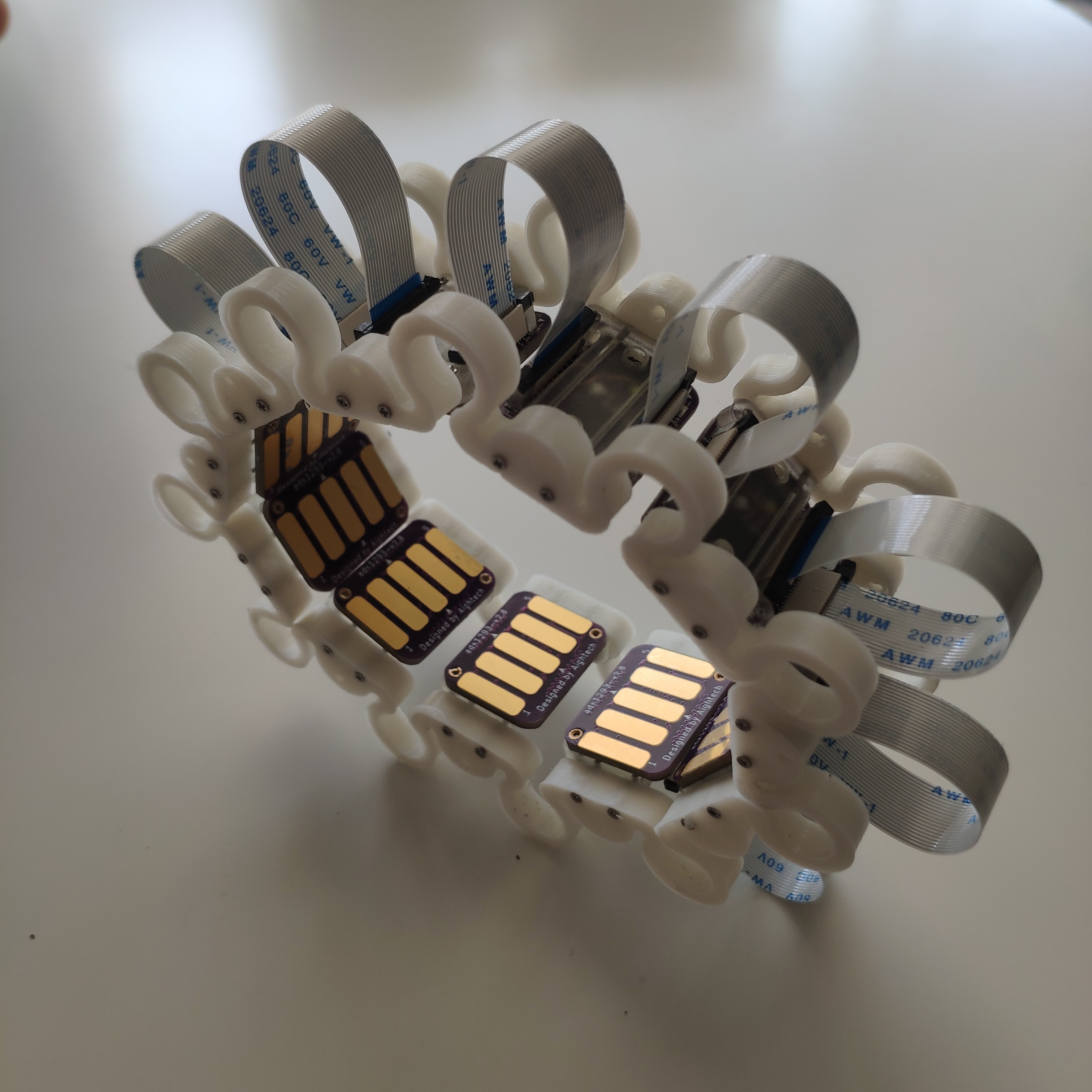
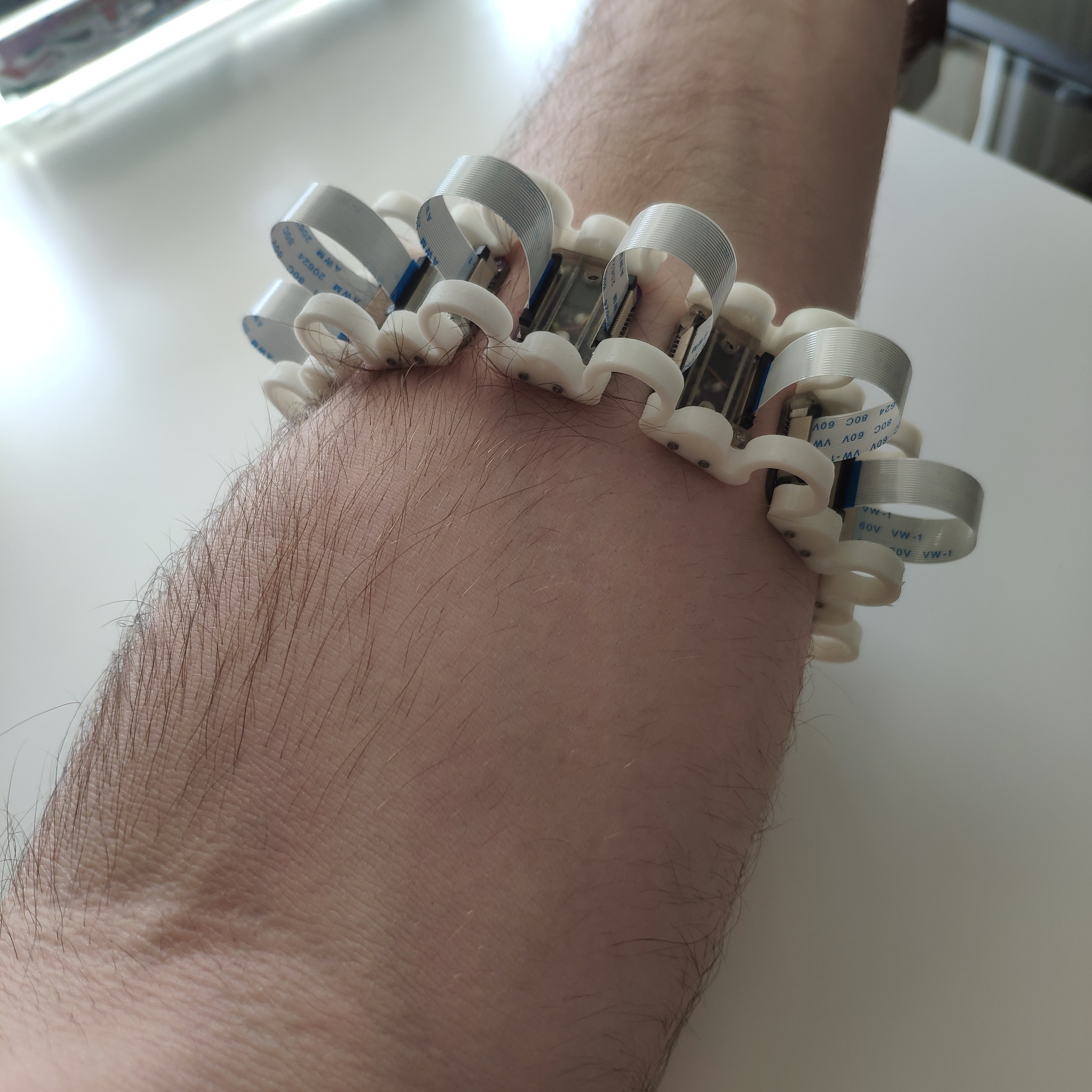
| Module | Bracelet factor |
|---|---|
 |
 |
Description
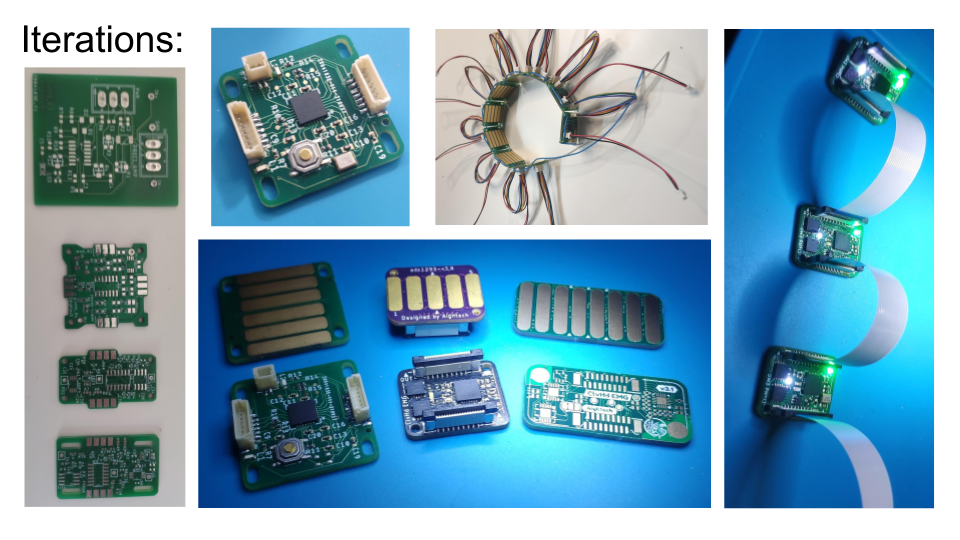
CleverHand is a low-cost, highly modular, and open-source Human-Machine Interface (HMI). This system offer the possibility to record and process bio-signals (EMG, ECG, EEG, etc.), kinematics data (accelerometer, gyroscope, magnetometer, etc.), and simultaneously provide a real-time feedback to the user (vibration, LED, Electro-stimulation, etc.). The system is based on a modular architecture, which allows the user to easily add or remove modules to adapt the system to his needs.
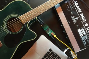
Cleverhand is deigned primarily for research and educational purposes. It allows the user to easily set up a wide range of experiments, from simple EMG recordings to complex Human-Machine Interaction (HMI) experiments.
Requirememts
| Constraint | Status | Comment |
| Wearable | Wifi feature in progress |
|
| >16 channels | Up to 256 channels (32x8) | |
| >2kHz bandwidth | Up to 2.5kHz | |
| >=16 bits resolution | Up to 24bits | |
| Bipolar/Monopolar | ||
| Modular | 1 to 32 modules by bus | |
| Affordable | <10-30£ per module | |
| Opensource |
Features
The system is composed of a controller module and a set of HMI modules.
Controller module
The controller module is the core of the system. It is responsible for the communication between the HMI modules and the computer. It is based on a microcontroller (Teensy 4.1) and a communication module (ESP32). The controller module is equipped with a USB, ethernet and WiFi interface, which allows the user to easily connect the system to a computer. The controller module is also equipped with a microSD card, which allows the user to store the data locally.
HMI modules
The HMI modules are responsible for the bio-signal acquisition and the real-time feedback. The HMI modules are themeseleves composed of several sub-modules, which can be easily connected to each other:
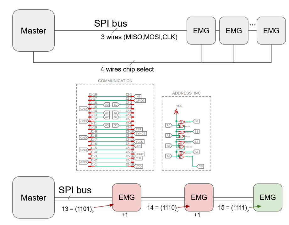
- Communication module: This sub-module is responsible for handling the communication between the different modules of the controller.
- Sensor module: This sub-module is responsible for acquiring the signals (EMG, ECG, EEG, IMU, etc.).
- Feedback module: This sub-module is responsible for providing a real-time feedback to the user (vibration, LED, Electro-stimulation, etc.).
- Electrode module: This sub-module is responsible for providing the interface between the sensor module and the user (electrodes, accelerometers, etc.).
- Interface module: This sub-module is responsible for extending the electrode module with additional features (Jack connector, flexible PCB, etc.).
List of modules
| Module | Description | Front | Back | Link |
|---|---|---|---|---|
| Communication | Handles the communication between the modules of the controller. |  |
 |
Link |
| EMG ADS1293 | Acquires 5 channels of EMG signals. |  |
 |
Link |
| EMG ADS1298 | Acquires 8 channels of EMG signals. |  |
 |
Link |
| EMG INA331 | Acquires 1 channel of EMG signals + 3-axis accelerometer. |  |
 |
Link |
| FES AO4882 | Provides 4 channels of electro-stimulation. |  |
 |
Link |
| IMU ICM2094 | Acquires 3-axis accelerometer, 3-axis gyroscope, 3-axis magnetometer. |  |
 |
Link |
| DRY Electrodes | Provides 16 channels of dry electrodes. |  |
 |
Link |
| DRY Flex | Provides 8 bipolar channels on a flexible PCB. |  |
 |
Link |
| Jack Connector | Provides a jack connector for the electrode module. |  |
 |
Link |
Combinaisons of sub-modules
The HMI modules can be easily combined to create a wide range of experiments. Here are some examples of combinaisons:
| Combination | Front | Back |
|---|---|---|
| Communication + EMG ADS1293 + DRY Electrodes |  |
 |
| Communication + EMG ADS1298 + DRY Electrodes |  |
 |
| Communication + EMG INA331 + DRY Electrodes |  |
 |
| Communication + FES AO4882 + DRY Electrodes |  |
 |
| Communication + IMU ICM2094 + EMG ADS1293 + DRY Electrodes |  |
 |
Modular architecture
The system uses a shared bus architecture, which allows the user to easily add or remove modules to adapt the system to...
Read more »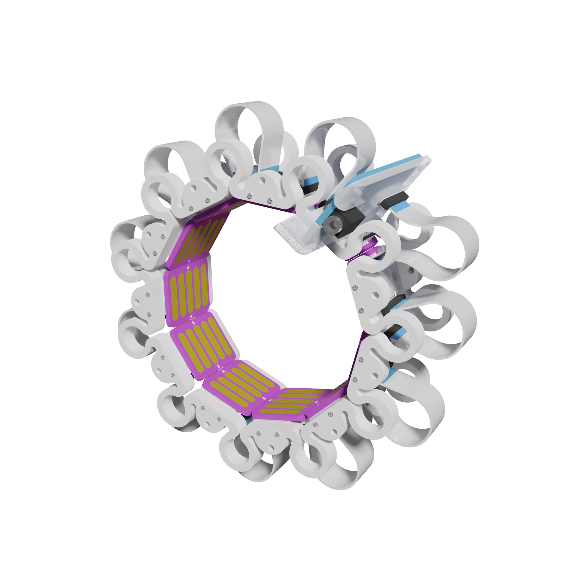
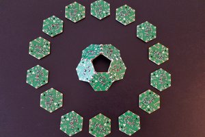
 Hexabitz
 Richard
 ACROBOTIC Industries