 Chris Jones
Before beginning here, obviously this is working with mains level voltages, charged capacitors and high current batteries that could likely injure or kill someone, this is not advised, and is very dangerous so I don't condone anyone to attempt this if you are not comfortable and understand the precautions..
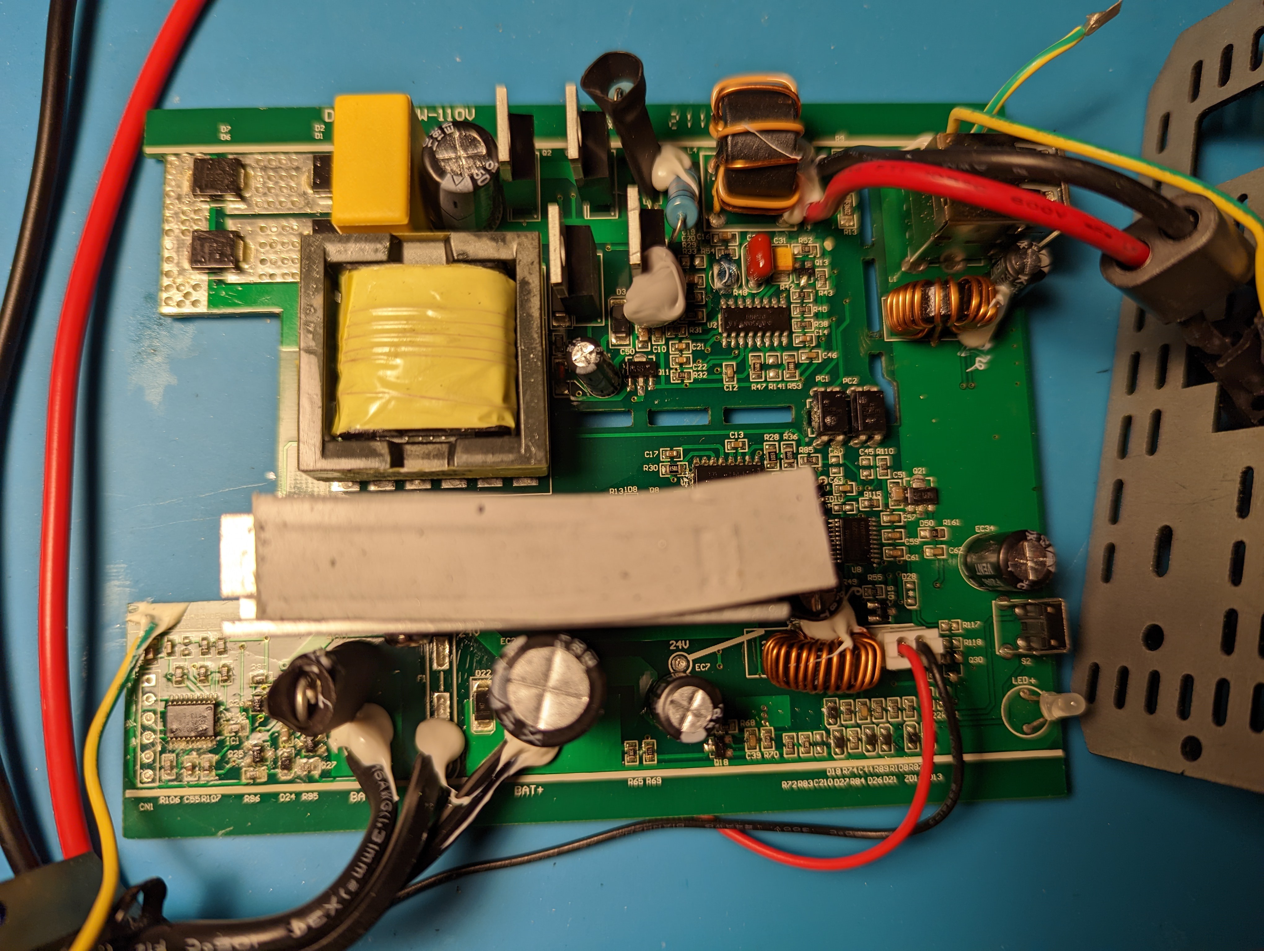
So after taking the unit apart it was clearly apparent that this was going to be far more complicated than I originally thought.
My first thought was I could try to reverse engineer the communication protocol, but after probing around a bit this seemed like it might not even be needed, plus that would require me to add an additional device if I wanted to use other batteries. So I wanted to stick with KISS and find out how this thing worked..
Tracing the signal wire from the COM wire input into the inverter PCB first led me to the lower left corner of the PCB. With conformal coating everywhere this proved to be a fun task to accomplish in itself.
My first thought was to try to figure out what chip this was and try to dig out a datasheet from the scourge of the the web..
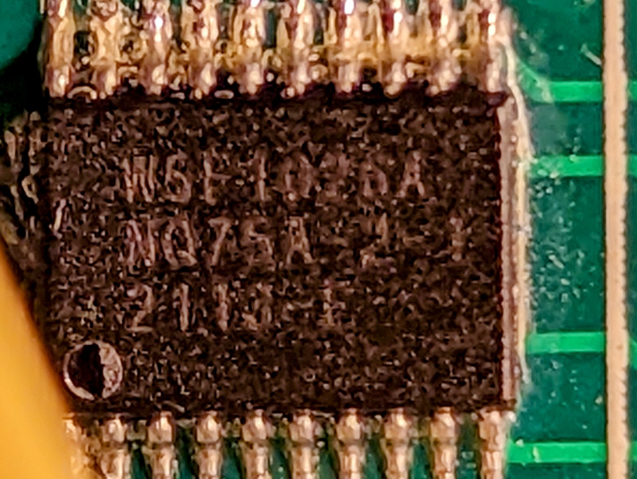
I managed to pull what I assume to be "W5F1026A" which gave me little to no information on the internet with only a archaic link to a Chinese company that manufactures a programing tool, but no data sheet or information about the chip.
So my circuit tracing continued.
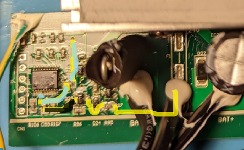
After tracing the 2 paths from the area above..
(Simplified trace of the signal from the COM to the mystery chip and what appeared to be a signal line light blue above to the 8051 chip)
I managed to trace it to the next chip.
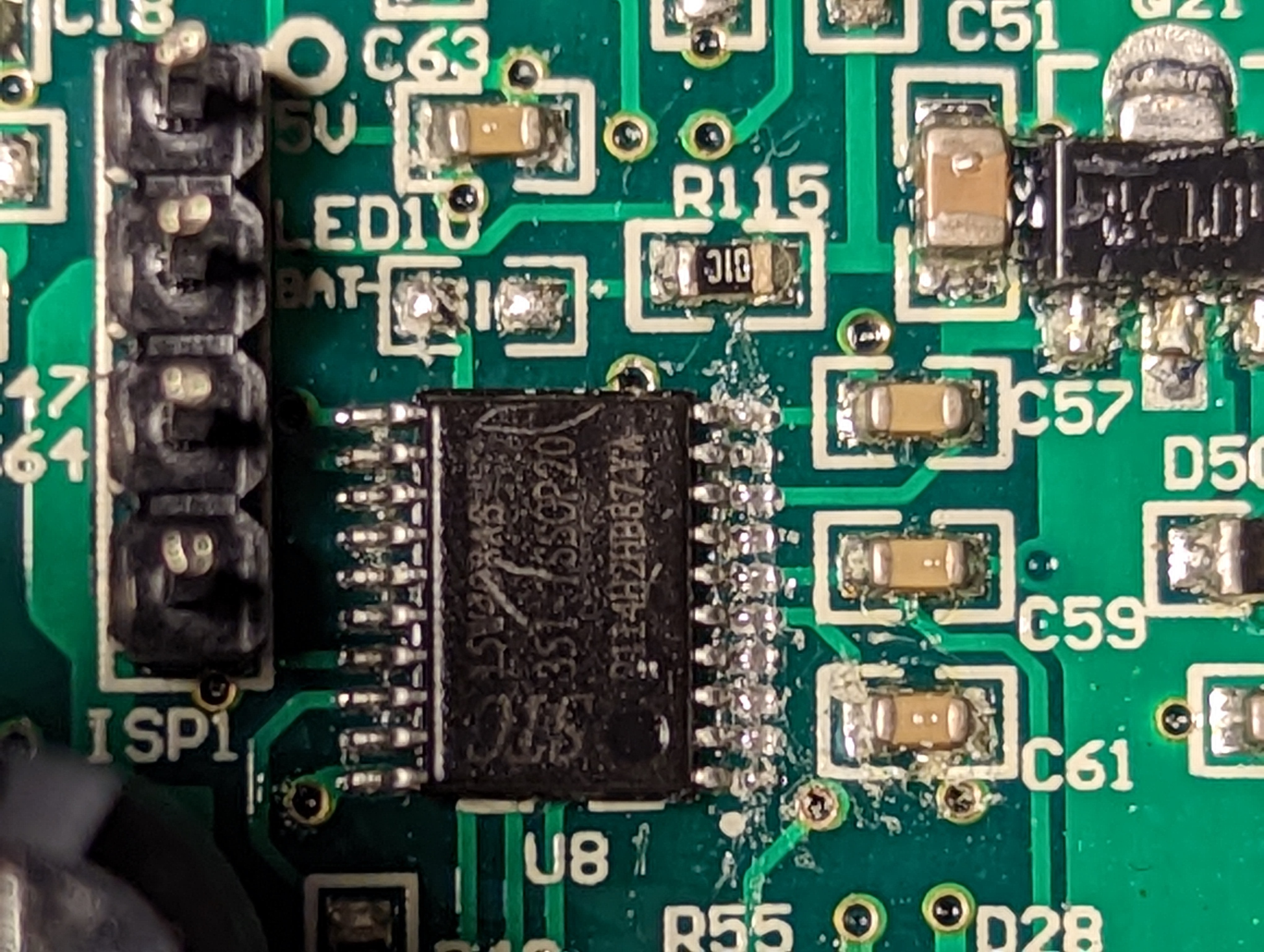
This one I had better luck of chasing down what it actually was and even locating a datasheet.
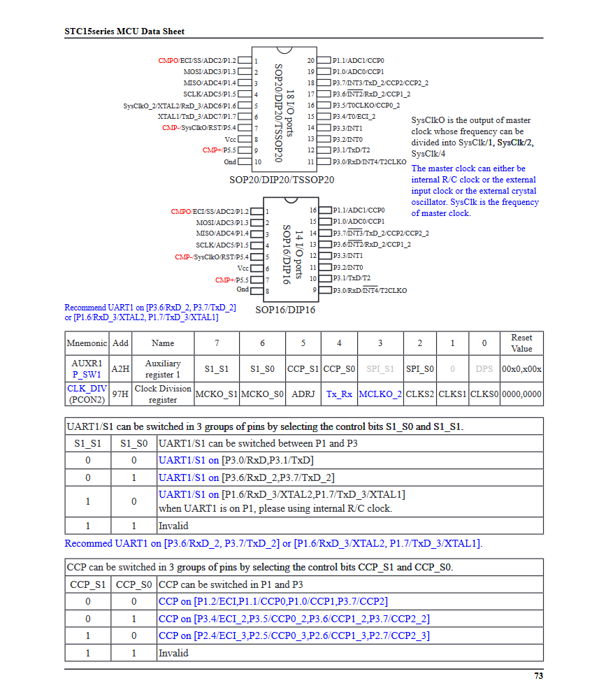
Which appeared to be an STC 8051 microcontroller.
This was helpful to start to see how things might be working.
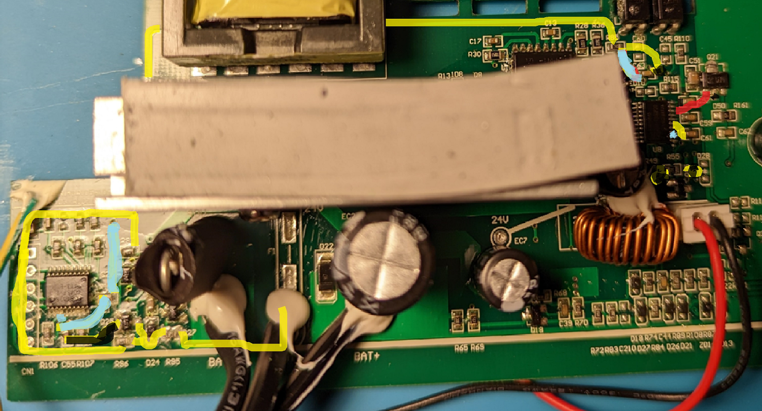
I was able to identify the vcc and ground which helped to see where the voltage regulator was and where we might be able to start carefully probing.
As indicated in the light blue and yellow I tested both in reference to ground with:
A. Battery connected, button not triggered
B. Battery connected, button triggered (short power on)
C. Battery connected, button triggered (fault mode post power on)
D. Battery connected, post fault mode / auto power off
This resulted in:
A. Yellow and Blue trace - 0v
B. Yellow trace - 5v and Blue trace - 0v
C. Yellow trace - 5v and Blue trace - 5v
D. Yellow and Blue trace - 0v
This led me to believe that the blue trace from the "mystery" chip might be a pull down to activate the 8051 microcontroller which might handle the actual logic for managing the inverter.
So I did what any hacker would do and I broke out the soldering iron and a resistor to see what might happen if I pulled the line low with a lower value resistor.
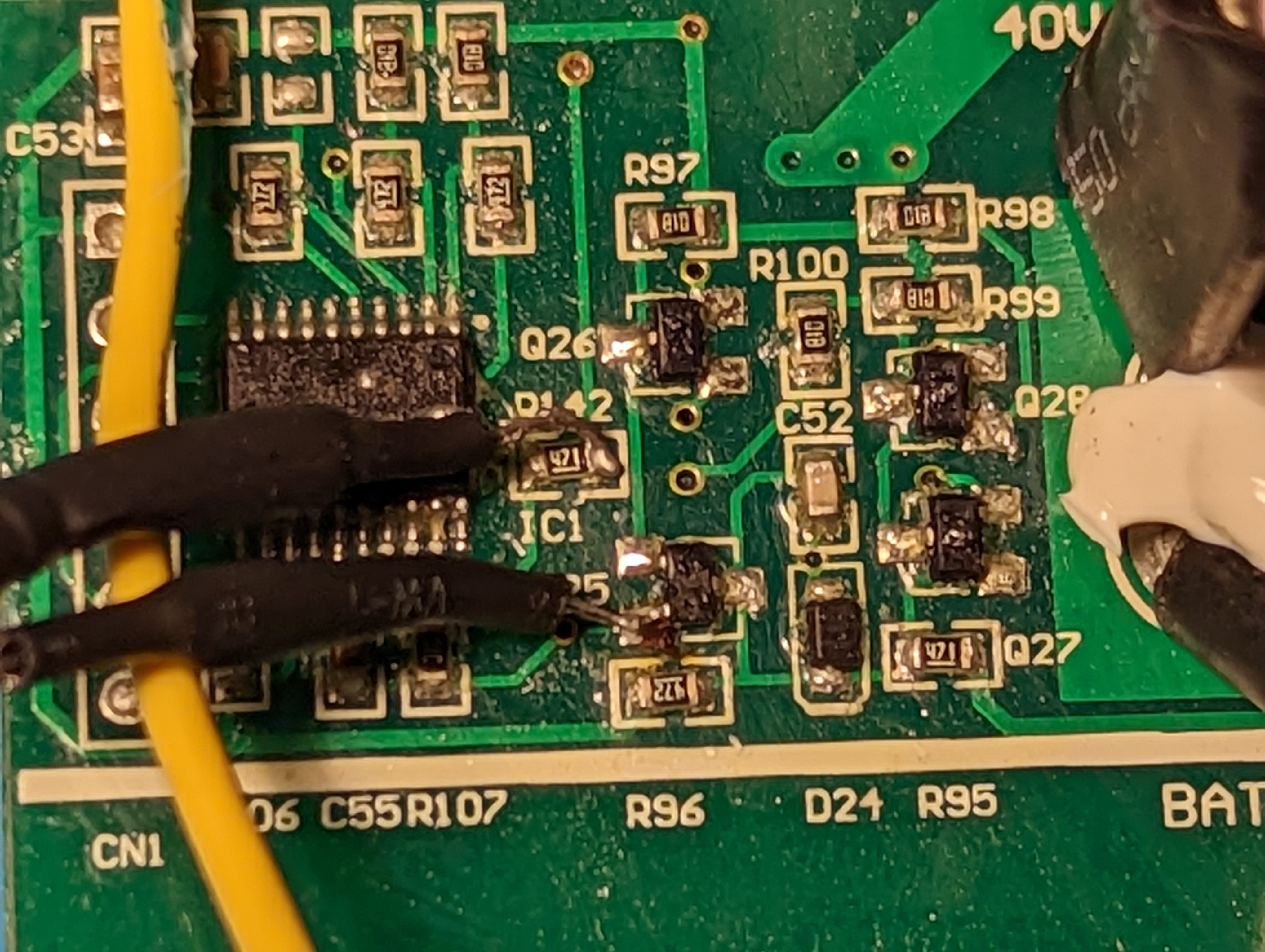
(270 ohm resistor connected across R142 471 ohm resistor end and Q25 transistor ground to pull down the signal line from the "mystery" chip and the 8051 microcontroller)
And after adding the 270 ohm resistor to the signal line as shown above and connecting the battery back and pressing the button, to my amazement, IT WORKED and stayed on!
After pressing the button again the unit turned off as well so it appeared everything was working..
After cleaning up my solder spots to remove any residual flux and putting down a generous glob of hot glue to make sure there was no stress put on the joints I reassembled the unit and it was good to go..
I tested it with every battery I had that matched the voltage range and didn't see any issues.
Discussions
Become a Hackaday.io Member
Create an account to leave a comment. Already have an account? Log In.