Close
0%
0%

DIY Mech/Exoskeleton suit.

Mechs are not viable, nor cheap, so I will try to design and build one alone anyway.

Public Chat
Similar projects worth following
Mechs are cool and I wasted a not trivial amount of time researching about related topics that I think are equally as cool and interesting.

I hope I can build one or more mechs, but first I need to actually project one.

I will try to list in this project here all the ideas I had/have because I'm noticing that I'm repeating the same cycle of ideas, and by putting these ideas on paper, I will finally just forget this mech thing and move on to better ways of using my time and effort, or just be completely consumed by it.

I'm not an engineer (thus the enthusiasm), neither a programmer, or any other actually useful professional expertise.

Everything I use and/or make is open-source.

Also², the Artist of the pic/painting of this project is "Ukitakumuki Kai Lim", you can find their profile on Devianart, the specific pic is called: "Project Boots: PANAM Armour" (and it is cool as heck).
And no, the artist is in not working in this project

Well, this project is pretty much dead.

I'm talking this "in the moment" so to speak, and I may or may not change my mind later.

But in summary: I'm broke.

It is unrealistic to simply think "I will be doing little by little" when I don't even have the money to buy the cheapest hydraulic gear pump.

It is not possible for me to simply make 3D models for physical objects that I don't even have the condition to buy and assemble, after all, even the screws are expensive (to me).

Yeah, I said in the project description that mechs are expensive, and I'm giving up on the project because I don't have the money for the cheapest mech/exosuit that I could think of.

There is probably someone out there with enough spare time, focus and money that could make this project a reality, but right now I feel that this person is not me.


---------------------------------------------------------------------------------------------------------------------------------------------


This is a guide, not a instruction's book.

Well, the idea of this project is to be more of a guide-book rather than a rule-book, I will make my own stuff, but it doesn't mean you can't learn other things that could be useful for your specific needs.

Plus, I'm not even an engineer, a professional would have finished this project a long time ago.

The project logs are long and counting up, my apologies for that, but if you want to really just start where the project truly starts, go to Project Log 54 forward.

Previous project logs are more or less about exploring every option that I could find and learning all the necessary stuff for the project rather than an actual manual.

That's why I think it could be relevant for you to read everything first if you aren't familiar with engineering in general, or if you just want to understand why I abandoned certain ideas and kept working with other.
During the project, I changed my mind a myriad of different times about how to build this thing, and in hindsight, I think it was for the best.

So I think it is worth making the choice of studying every option before actually committing to build it. I saved so much money that I would otherwise have expended for dead ends that I didn't knew it were dead ends.

Right now I'm writing Project Log 68, so I'm more or less on the "final steps" before actually building the thing itself.

Again, this is not a "connect part 2B with part 3A in this way", this is more of a "I connected part 1, 2 and 3 this way because I think it would be stronger and easier to build, if there is a better way, I don't know, but I heard that you could connect these parts in a X configuration, which I never tested before" kind of DIY guide.


Index:

    Bearing.zip

    DIY Slew Bearing for Exoskeleton as stated on Project Log 69: https://hackaday.io/project/188391-diy-mechexoskeleton-suit/log/222406-project-log-69-diy-endoskeleton-and-exoskeleton It is a blender archive compressed in a zip archive, which I should have done sooner.

    x-zip-compressed - 39.45 MB - 09/20/2023 at 21:07

    Download

    Electric motor.zip

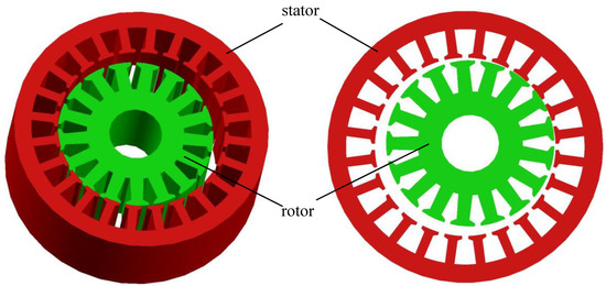
    3D models of the DIY electric motors mentioned on Project Log 58: https://hackaday.io/project/188391-diy-mechexoskeleton-suit/log/220958-project-log-58-diy-electric-motor

    x-zip-compressed - 23.72 MB - 09/11/2023 at 17:20

    Download

    DIY Hydraulic Pump - 1, 2 & 3.zip

    Mold for stator, gearbox, "motorbox" and hydraulic pump as stated in Project Log 68: https://hackaday.io/project/188391-diy-mechexoskeleton-suit/log/222346-project-log-68-diy-hydraulic-pump (Hackaday limits singular archives to be uploaded to 50mb, so I compressed to this one here)

    x-zip-compressed - 36.26 MB - 09/11/2023 at 17:17

    Download

    • Project Log 73: DIY Endoskeleton and Exoskeleton.²

      FulanoDetail09/13/2023 at 15:35 1 comment

      Wednesday, 13/09/2023, 12:13

      I'm feeling like whatever the hell I wrote in these "serious" project logs are complete nonsense, not only because I'm talking things with almost no basis in fact, but also because it looks like writings of a mad man.

      I was simply trying to read previous project logs and I mix texts were I wrote it in the past and parts that I wrote in the present, so I may be referring to something like I'm talking about "the previous subject matter" but there are multiple paragraphs referring to something completly different.

      ... Which makes me wanna make more project logs that are more organized...

      ... But I'm holding myself to not do such bullshitery simply because I didn't finish the goddang 3D models yet.


      -----------------------------------------------------------------------------------------------------------------------------------------------


      Well... Hi, good day, good afternoon and good night.

      I'm still in an awful mood, but I would guess that it would be useful to simply do something (anything) rather than do nothing.

      And well...  I'm just going to post here everything I need to watch so I stop procrastinating...


      ... It is kinda funny how I plainly said that this project is dead on Project Details, but I keep going with the project.


      Being honest, if I had the money, I would've pay someone actually skilled to make this project a reality instead of cracking my head against the wall...


      To be honest², even though I'm watching video per video, I'm not understanding half of the stuff that I'm looking at.

      ... I really need help with this project...


      -----------------------------------------------------------------------------------------------------------------------------------------------


      Also, one thing that I forgot to talk about in all these project logs: remelting of 3D printed parts.

      Basically, you could 3D print parts with 100% infill, put them in a medium such as plaster/gypsum and then put the thing inside an oven with more or less the melting point of the plastic being used and take it out.

      Basically, 3D prints have a problem of layer adhesion, meaning that all 3D printed parts are basically a pile of sheets of paper-thin plastic layers held together by the adhesion of its surface.

      By remelting the parts, you are turning the entire thing in one solid piece of plastic.

      I saw other methods that use salt instead of plaster.


      In anyway, you could commission 3D printed parts on a plastic of your choosing (such as HDPE) on one of those 3D print online stores and use this method to make the parts stronger.

      Plus, you could drill the parts and infuse them with fillers such as steel wire and such.

      Or just embed the wire on the 3D print during printing. lol


      I just saw this video from the same channel, it is another interesting option.

      Although carbon fiber is expensive, glass fiber isn't that much.


      You could use either method to make the 3d printed parts stronger:

      • Drill holes and inserting the steel wires and remelting.
      • Drill holes and inserting carbon fiber/glass fiber and remelting.
      • Injecting epoxy with glass/carbon fiber in the 3D print.

      -----------------------------------------------------------------------------------------------------------------------------------------------


      Well, I was looking into buying slew bearings and make copies of them, and while I was doing that I stumbled upon this video.

      I don't know what material it uses for the flat bearing plates that it has, but I thought it was an interesting concept.

      Plus, I did like the idea of inserting limiters on the ring in order to, well, limit its rotation.


      This means that the bearings that I've made aren't suitable as the way they are now, I need to remake them with a better concept in mind.

      ... Read more »

    • Project Log 72: DIY Hydraulic Pump.²

      FulanoDetail09/03/2023 at 16:31 4 comments

      03/09/2023, 13:20, Sunday.

      Well, I'm writing this² after finishing this project log because I feel like I failed this project log.

      Even though I reached a few conclusions on how much energy I would require depending on the type of pump I used, I didn't reach any satisfactory conclusion.

      Neither did I make any useful 3D model.

      I will try again later and maybe this little message will be deleted, but still.


      ----------------------------------------------------------------------------------------------------------------------------------------------


      So, I'm writting this here because I had some ideas for making a cheap DIY pump, my stupid brain simply insists that I'm simply not trying hard enough when there is simply no easy way of doing these kinds of things.


      ----------------------------------------------------------------------------------------------------------------------------------------------


      Well, where do I start?

      I was checking some other solenoid valves that aren't 5kg of force, and decided to at least give a try with the 25 newton solenoids.

      This one weights 100 grams, but I would bet it is more likely because of the steel part rather than the copper coil.
      In either way, you could use aluminium wire instead of copper, but it is a little bit cheaper per kg than copper.

      Anyway, this one uses 4.8 watts of power, but in some sites it says it uses 30 watts.

      So I thought on making a free piston/plunger with 7mm to 8mm of diameter (needing a force of 19 Newtons to 25 Newtons respectively) moving 50 times a second, it will be able to achieve 1.5 liters per minute in each side of the pump, so 3 liters per minute in total.
      This would be able to more or less actuate two filament artificial muscles, however, if you braid those like intended, you would use longer muscles that in turn would need more fluid flow.

      Now, for the working principle you have two options:

      1. Using a soft iron core with two coils that will alternatively pull the free piston torwards in alternating turns.
      2. Using a Neodymium magnet as the free piston with a single coil that will change the electromagnetic poles, making the magnet move up or down.

      Both have advantages and disadvantages, but let's remember that this thing will be moving 50 times a second, I'm confident the iron core can handle it, but I don't know about the neodymium magnet.

      In both cases you will need a way of knowing where the free piston is, using some kind of sensor.

      First I thought on using a hall sensor or a mechanical switch, but the hall sensor has to take into consideration the electromagnetic field and the mechanical switch has to take into consideration the pressure inside the chamber, so it doesn't activate with the pressure.

      I'm pretty sure there is a easier way of doing that, but I couldn't think of anything.


      With a 1kg of copper and 100gram coil per solenoid pump consuming around 30 watts of power, you would be able to power 20 muscles, or in the worst case, 10 muscles.

      Since 1kg of copper wire is 100 reais (20 dollars), you would use 1500 to 3000 reais (300 to 600 dollars) in total. Not so dissimilar than the 10 dollar brushless motor.

      But the downside of the brushless motor is that it needs a reduction gear and a very bulky hydraulic gear pump.


      ----------------------------------------------------------------------------------------------------------------------------------------------


      Now, about the hydraulic gear pump and/or the axial piston pump.

      One thing I was very clear on talking about was the precision between the parts, which I don't really think it would be easier (or possible) to do in a DIY way.

      The idea would be to simply do two things:

      1. Using a glass plate with abrasive material on it.
      2. And/or using a DIY lathe.

      The glass is the flatest surface that one could have at home, so by using it like a "sand paper", you could achieve incredibly...

      Read more »

    • Project Log 71: DIY Linear Actuator.⁴

      FulanoDetail08/24/2023 at 12:07 3 comments

      Thursday, 08:31, 24/08/2023

      Well, morning.

      By the time that I actually start making the exo/endo-skeleton, it will be buried under 3983932382 project logs.

      ... But I think this is relevant, because I need to talk about Dielectric Elastomers and I already wrote so much crap on the previous project logs about linear actuators that hackaday simply starts deleting new text on them.


      Just to recaptulate:

      The hydraulic artificial muscle system, although being lighter and allowing a higher efficiency, since it is lighter than metal hydraulic cylinders, its oil still weights a lot.
      More or less 180kg to 225kg.

      So I thought "hey, since I'm already facing such inneficiencies with such system, then why not try something else?"

      Then I calculated pneumatics, but those are inneficient as heck and quite dangerous to work with.

      Then I thought on Dielectric Elastomer Actuators, those wouldn't need an electric to mechanical to hydraulic conversion and make a somewhat efficient system, even if these aren't that efficient in the first place.


      In any way, I was absolutely sure about the efficiency of dielectric elastomers to be really low, but after looking into some review papers of dieletric elastomers, I'm not so sure.

      You see, for some reason, when I look at dielectric elastomers review papers (such as the one bellow), they always say that the efficiency of DEA's are around 80% to 90%.

      https://onlinelibrary.wiley.com/doi/epdf/10.1002/aisy.202000282

      ... But when I "ask around" and/or search for specific articles with new DEA's, it is always something bellow 40% efficiency.

      And the problem is: when I try to look into the bibliographic sources these review articles use, instead of leading me to specific studies, they send me to older review papers with the same efficiency reference and I can't find the actual production method.

      Bro, I'm reading articles from the early 2000's and I still didn't find a single fricking method of production (or I simply didn't pay enough attention, I have ADHD after all).

      The article in question: 

      https://link.springer.com/article/10.1557/PROC-600-119

      You will need sci-hub to see it, but basically, it says it uses something related to acrylic.


      In either way, there are 2 options here:

      • Either I'm simply not reading the full information (since I'm literally fast scrolling though everything, that's my fault).
      • Either some articles simply take references without double-checking their sources (which is doubtful).
      • Either they are talking about dielectrict elastomer generators (that convert mechanical energy into electrical) instead of actuators.

      A 4th option would be that the movement that the dielectric elastomer makes is highly efficient, but the elasticity of the material reduces the efficiency.

      Most of the dielectric elastomers have a really low actuation, in the milimeters of actuation, so they need to make a reversebly actuated artificial muscle, just like the hydraulic ones I was thinking on making.

      And thus, the necessity of making the muscle relax when voltage is on and contract when the voltage is off means a low efficiency of energy transmission.


      Also, I thought on two ways of making dielectric elastomer artificial muscles systems.

      Basically, I either do the reversebly actuated or the membrane actuated.

      At more or less 2:11 time in the video, you can see how big it is the actuation of the membrane, if you were to pass a shaft/rope through the membrane and stacked a lof of these membranes, you could make an artificial muscle pull it up.

      Something akin to this, but with a rope instead of a rigid shaft.

      Now, the reversibly actuated you already know: you make a strand, when voltage is on, the strand relaxes, increasing length, and once the voltage is off, the strand contracts.


      Or maybe neither of these, but continuum design (aka tentacles):


      I posted it at the...

      Read more »

    • Project Log 70: DIY Hydrogen Fuel Cell.⁴

      FulanoDetail08/21/2023 at 11:51 0 comments

      Monday, 21/08/2023, 08:09.

      Well, my apologies, but I think I found something interesting. Basically, you can store hydrogen gas in solid Naphthalene.

      (I feel like someone told me about this before and I stupidly ignored them, but I don't quite remember)


      As you may remember, I kinda gave up on the idea of using hydrogen as a fuel because hydrogen is pretty difficult to store, you either need carbon fiber 700 bar (70 MPa) pressure hydrogen gas tanks (which are expensive) or metal hydrides (which are triple expensive), but I think I found something interesting.

      ChatGPT is kinda annoying to work with, because you really need to make the right questions in the right order to get the information that you need.

      And it never cared to explain that there are other ways of storing hydrogen on solid compounds besides metal hydrides.


      Let's also remember that ChatGPT can be strongly incorrect about a subject.

      Although it told me a lot, every time I try to get a useful information, it keeps saying that his knowledge was cut in 2021 and tells me to update to the premium version.

      Basically telling me to screw off unless I have money.


      For example, it first told me that you could store 66kg of hydrogen gas in 1kg of naphthalene, then I asked if he was correct and then changed to 6% of hydrogen per kg of Naphthalene.

      You could also store it on activated carbon and/or titanium powder, but it would be around 1 to 2% per kg.


      "Yes, there are liquids that can dissolve and store hydrogen gas. One example is organic liquids that are highly hydrogenated and have a high solubility for hydrogen gas. These liquids are often referred to as "liquid organic hydrogen carriers" (LOHCs). LOHCs are typically organic compounds that can reversibly bind and release hydrogen gas through chemical reactions.
      Here's how the process generally works:
      1. Absorption: The LOHC molecule reacts with hydrogen gas to form a hydrogenated version of the molecule.
      2. Storage: The hydrogenated LOHC is stable and can be stored at room temperature and atmospheric pressure.
      3. Desorption: When needed, the hydrogen gas can be released from the hydrogenated LOHC by reversing the reaction, which typically requires adding energy (e.g., heat).
      The advantage of using LOHCs is that they offer a way to store and transport hydrogen gas without the need for high-pressure tanks, which are often required for storing gaseous hydrogen. This can enhance the safety and practicality of hydrogen storage and transportation.
      Another example is using certain ionic liquids, which are salts that are liquid at relatively low temperatures, as solvents for hydrogen gas. These ionic liquids can interact with hydrogen molecules and store them within their structure. However, research in this area is still ongoing, and there are challenges to be addressed, including finding suitable ionic liquids that exhibit high hydrogen solubility and stability.
      It's worth noting that while hydrogen gas can be dissolved in these liquids, the storage capacity may be limited compared to other storage methods like metal hydrides or compressed gas storage. The field of hydrogen storage is an active area of research, and scientists are exploring various materials and methods to make hydrogen storage more efficient, safe, and practical."

      "Certainly, here's a list of some common Liquid Organic Hydrogen Carriers (LOHCs) that have been researched for hydrogen storage:

      1. Dibenzyltoluene (H12-DBT): This is one of the earliest and most well-known LOHCs. It can react with hydrogen to form hydrogenated dibenzyltoluene, and the hydrogen can be released by applying heat.
      2. Methylcyclohexane (MCH): Methylcyclohexane can undergo reversible hydrogenation to form methylcyclohexane with hydrogen. The process is facilitated by catalysts, and the hydrogen can be released by dehydrogenation.
      3. Tetrahydroquinoline (THQ): THQ can react with hydrogen to form hydrogenated tetrahydroquinoline,...
      Read more »

    • Project Log 69: DIY Endoskeleton and Exoskeleton.¹

      FulanoDetail08/20/2023 at 18:08 2 comments

      Sunday, 20/08/2023, 15:02

      There is no way I wil be able to finish this project log in a single day or even a single week, so I will just post this here, so if someone wonders "is this project still being actively worked on?" then, they will know that I'm just bashing my head against the keyboard trying to finish this damn thing.


      ---------------------------------------------------------------------------------------------------------------------------------


      Now the hardest part of the project: the endoskeleton/exoskeleton.

      In simple terms, I will have to make an skeleton for both the Mech (thus, "endoskeleton") and for the exosuit (thus, the exoskeleton).

      Although it would be tempting to simply go Ctrl+C and Ctrl+V on the human skeleton 3D models, it wouldn't be that useful for this role in specific (to be used as a mech) because the human body has a complex and numerous ligments, joints, tendons and muscles that you can't really replicate on a mech/exoskeleton very easily.

      As cool as the Nanosuit or EVA bio-mech looks like, you would need to make sure more than 650 completely different types of skeletal muscles are working properly and/or aren't damaged in someway. Not to mention on how the hell you're going to realistically control and actuate all muscles in a fast and dynamic way.

      Now compare it to this DIY mech/exosuit where all the muscles are exactly the same, but only change in force/pressure and quantity depending on the limb.
      It orders of magnitute easier to build and/or maintain that.

      But if even then you want to try it yourself, I suggest you give a look at anatomy videos:

      https://www.youtube.com/@AnatomyLab/playlist


      ---------------------------------------------------------------------------------------------------------------------------------


      Anyway, I will try to make the Endoskeleton more or less the way you would make a Stewart platform with artificial muscles (and a little like the Project Boots, the picture of this project). And maybe make the arms a little more "anatomy based" simply because they need to be more dexterous than the legs and use less force.

      I mean, with a stewart platform shoulder-arm-elbow you can't even completly lift your arm (I think).

      Also, if you didn't saw the full image of this project's picture, check this:

      Source (I mean, I already linked the source on the project itself): 
      https://www.deviantart.com/ukitakumuki/art/Project-Boots-PANAM-Armour-492940388


      --------------------------------


      Now, the exoskeleton is another matter...

      I will try to make it like the deep dive suits, where the hinges are actually rotating bearings on diagonals that allows for a full enclosed suit with a completly rigid outer shell. Then I will add an extra layer to that in order to attach the muscle strands in a similar way to the stewart platform and also do avoid the range of movement that doesn't harm the person inside of it.
      You will be using artificial muscles with load capacities over 300kg to 3000kg of force (depending on how strong you want your suit to be), every care is necessary.

      Ironically, a lot of these deep diving suits (up to 600 meters of depth in the ocean) are actually made out of glass/kevlar fiber composites (obviously, they are made by very qualified people), so you could try making your own versions like that.

      But for the love of god, at least test the structure before using the goddamn suit.


      The video bellow are simply astronaut suits that more or less work in a similar manner, not totally like what I'm suggesting tho.

      Also, Adam savage is kinda cool.

      https://www.youtube.com/@tested/playlists
      (I tried to post the playlist for his space suit videos, but it only shows a single video instead of the complete playlist, he does some builds that actually use these angled bearing joints)

      Also, he makes the space suit-like things with wood and cloth, which is readly accessible for anyone and on top of that,...

      Read more »

    • Project Log 68: DIY Hydraulic Pump.¹

      FulanoDetail08/18/2023 at 13:47 4 comments

      Friday, 18/08/2023, 10:39

      Well, I need to write this somewhere before I forget.
      About the controls of the mech/exoskeleton: I was thinking on using James Bruton's hall sensors idea of adding them to a rubber case, but I was also thinking on that the hall sensors would be programed to make the exoskeleton to move like it is trying to repel the hall sensors, so it will always instantaneously follow the human body and feel like it is weightless.

      Well, this would only be useful in an exoskeleton, a mech with a person inside of it wouldn't have that much room for movement (depending on the design).

      And I don't know how well this would work as an exoskeleton either, since the exoskeleton will always be trying to avoid the center, then it won't be supporting the user's weight.
      But I won't heat my head over this simply because this is hard even for actual engineers working on exoskeletons around the world.

      (I feel like I already wrote this on previous project logs)


      ------------------------------------------------------------------------------------------------------------------------------------------


      Well, my gals and pals and goblins such as me.

      Last project log I found out that micro-solenoid pump are actually viable, so in this project log I will 3D model what I think it will be necessary for the construction and working of the reversebly actuated hydraulic artificial muscles (RAHAM), starting with its pump.

      So, just listing it:

      - Micro Pumps 3D model (both piston and solenoid types).
      - Alternating One-way Valves (AOV) 3D model.
      - Molds for rubber tubes 3D model.


      -----------------------------------------------------------------------------------

      Also, I got an answer from a seller saying he would make an special link for me selling 180 reais (around 36 dollars) with 10kg of 1 meter long latex tubes, but when I clicked on his link, it was around 18,000 reais. Just bruh.

      (but I still feel a little guilty for not buying from him)
      -----------------------------------------------------------------------------------


      I would need 150 solenoid pumps, but I need to do twice the number of that since each pump has 2 coils.

      So, taking into consideration the proportions of the the pump we will be using, I would need a 10mm long 10mm wide shaft that would travel in total 20mm with the two coils.

      I will try to buy and copy a 5kg (50 newtons) solenoid actuator and copy it, but with a few differences.

      For one, I need to figure out how wide and how long the coil and core should be in order to achieve the desired actuation parameters.

      Not to mention that I also need to fit two alternating one-way valves into the design and be as compact as possible.

      However, I think it would be beneficial to use the following system as shown in the video bellow instead of using solenoids (for the valve):

      Worst part is that I tore open a bunch of old electronics at my house and I threw alway all of their relays because I couldn't extract the iron soft core...

      Now I need to find more electronic scrap...

      Also, one thing I forgot to say: the idea of the micropump and the artificial muscles is that every bundle of muscle and pumps would be inside a bag full of hydraulic fluid (not that full, because these don't need that much fluid).
      This way I could lubricate the sleeves/outside of the muscles and cool down the solenoid coils.


      Even though I've been excited with the solenoid coils, these aren't that efficient either. A 300 watt electric motor moving a piston hydraulic pump (with the dimensions discussed on Project Log 66) would be able to achieve around 57 liters per minute, while the solenoid pump would achieve around 10 liters per minute.

      ... But each brushless motor pump would need to be made with laminations, permanent magnets, coils and ESC's on top of making the solid metal hydraulic pump... Which all have weight.
      ... While a solenoid just needs two coils to be rounded up and a...

      Read more »

    • Project Log 67: DIY Linear Actuator.³

      FulanoDetail08/13/2023 at 13:58 0 comments

      Sunday, 13/08/2023, 10:55.

      I can't believe I'm saying this, but I think I will go back to the reversibly actuated artificial muscles.

      Yes, I know, I know, I just wasted so much time taking each single approach for their efficiency and now I'm throwing everything away (again) for reasons (sometimes I think I just keep remaking decisions every time I face a problem because deep inside I don't want to get my butt off the chair and to this stupid thing [not to mention how ridiculous it is that every time I say "I will just make both options" and end up making no option at all {and every time it happens I have some kind of existential crisis for some reason}]).

      Reversibly actuated hydraulic artificial muscles and hydraulic McKibben artificial muscles are only 60% efficient compared to hydraulic cylinders, which are 95% efficient.

      ... But the high efficiency come with a cost (not only monetary cost), they are heavy, bulky, difficult to produce (in a DIY way) and require high precision (for a DIY setup).
      Reversibly actuated hydraulic muscles on the other hand are just a tube of elastic material wrapped in fishing line. And still get 60% of efficiency.

      I calculated that I would need 3 kilometers of latex tubes, which would weight 15kg in total, while the hydraulic cylinders on total would weight around 100kg to 300kg. Which would mean that the mech/exosuit would waste more energy carrying this extra weight around, reducing the efficiency of the system.

      So even high efficiency actuators make the overrall system more inneficient, while the inneficient actuators make the system more efficient.

      Kinda ironic...


      Just to recapitulate what I'm talking about:

      By the way, since this kind of artificial muscle has 300% of stroke (3 times its initial length), then this means that it can be used just like the telescopic linear actuators. Which would be a positive... If I actually 3D modelled the exoskeleton/mech in the first place instead of just writting about it for hundreds of pages. :|


      In any way, this means that now I need fo find a way of making a lot of tension springs and/or elastic rubber bands.

      The reversibly actuated hydraulic artificial muscle (I will start calling this just "RAHAM" actuators) works by increasing the pressure with a fluid (air or hydraulic), but making the elastic element elongate, once the pressure is released, the spring element returns to its original shape.

      I'm saying "spring element" because you don't really need to use only a tube of elastic rubber/latex, you could use a literal cylinder and calculate the force applied to the cylinder head/base of the thing.


      One of the reasons that I gave up on the idea too early was the fact that it needs to keep all the actuators constantly under tension/pressure, which can diminish the life span of the RAHAM actuators.

      However, I believe that this problem in specific could be solved by simply enlogating the elastic element bellow its capacity, just like you wouldn't work with an engine on its maximum load for much longer.

      However, the only problem with this approach is that I need to find a way of containing the fluid in a flexible but resilient material and a way of "DIYing" the elastic elements.

      On the impact-dampening of the hydraulic actuators, I was thinking on simply filling the spring element with air, but I can't do that for a tension spring element. 

      Spring/rubber bands are accessible, but I would need absurd quantities of such material in a RAHAM mech/suit, so I need to think in a way of making DIY springs, which is a challange on itself. And I think that using springs would increase the overrall efficiency of the system, since it would make everything closer to a hydraulic cylinder instead of an artificial muscle.

      The source of the above image: https://www.industrialheating.com/articles/97520-c-c-composite-springs-and-their-applications

      (it has useful information on the...

      Read more »

    • Project Log 66: DIY Linear Actuator.²

      FulanoDetail07/27/2023 at 13:57 0 comments

      Thursday, 27/07/2023, 10:48.

      Well, I will just post this here, but I will keep editing later (I can barely edit anymore because I already wrote so much stuff).

      Just because It would be of great help if someone were to give suggestions.


      Even though I stuffed this project log with options, I'm still divided between hydraulics and the hoist mechanism.

      Hydraulics are a proven design in the real world and it has a lot of information on the subject, but it needs a lot of precision to avoid leaks. Precision that I may or may not be able to achieve in a DIY setup.
      I asked online if making high precision hydraulics using molds would be realistically, people answered that cylinder fail can lead to death and on top of that, casted parts need furthuer machining to meed required tolerances (PS: I don't know what are th required tolerances).

      The hoist linear mechanism is cheap and easy to make, but it doesn't have a proven design/example on the real world, and thus, I can't find a proper way of calculating its efficiency, and even if the efficiency was to be good, I still don't know how long its mechanical pieces would last...

      We are talking about 3000kg of force/weight being deposited in a DIY mechanical system, an hydraulic one would take the force easily, but a mechanical one...

      What do I do now?


      ----------------------------------------------------------------------------------------------------------------------------------


      Well, there was a giant text here talking a myriad of things about linear actuators, but in the end it was the same problem that I always make with my project logs: I keep posting random ideas and random videos that I found and I never actually finish the actual 3D model that I'm supposed to do.

       I will try to 3D model something similar to this, then, later I will try to make a telescopic actuator.


      ---------------------------------------------------------------------------------------------------------------------------------

      One thing that is kinda chipping off my mind is the twisting motions that the linear motor would suffer under loads, this is already a significant problem for conventional linear motors, now imagine a telescopic one, were each part would be support by a little bit of contact metal.

      How do I avoid such thing? I am overthinking its impacts on the structure? After all, everything will be in a stewart platform with universal joints, and on top of it, all the objects would have at least 10mm of thickness for extra resilience...

      I was actually thinking on make something akin to this, but with hoists instead of a belt drive, since belt drives aren't meant for high torque appliactions.


      Also, I was wondering if scissor actuators would be a good choice... They are even more compact than telescopic actuators, and quite simple aswell...

      This circular scissor mechanism actuates by rotating one of the two plates at the bottom and/or at the top, increasing or decreasing the angle between the scissor linkages.

      Althought I think it is an incredible type of mechanism, I don't really know if it faces the same problems as conventional scissor mechanisms (explained in the paragraph bellow) or if it is simply too complex.

      Source: http://robotics.estec.esa.int/ASTRA/Astra2006/Papers/ASTRA2006-2.3.1.01.pdf


      I was seriously giving this mechanism a thought, since after messing with an online calculator, I found out that the bigger the amount of degrees (past 45º), the less force you need to lift/ push the load.

      However, bellow 45º angle, the more and more force you need to apply in order to lift something, for example, at 5º I would need 35 tons of force to lift 3 tons.

      It would only be an efficient option if the device were designed to stay at the start at 45º.


      Maybe this is a solution?

      Of course, just replace...

      Read more »

    • Project Log 65: DIY Iron-Air Battery.²

      FulanoDetail07/21/2023 at 21:53 0 comments

      21/07/2023, Friday, 18:50.

      Well, hello, this is me from the future and I need to add some informations about Iron-Air battery.

      The theoretical energy density of iron-air battery is in the range of 1200 wh/kg and I optimiscally assumed that I could achieve at least 1000 wh/kg, which may or may not be too unrealistic.

      From what I could find, even in the best laboratory attempts, the iron-air battery "only" achieved at best 750 wh/kg of energy density and conventional attempts achieved "only" 300 wh/kg (still higher than lithium-ion batteries [250 wh/kg], but far away from 1000wh/kg).

      Even if I were to crush catalytic converters to use as catalysts, this is still a DIY setup and I doubt I would achieve crazy values such as 700 to 1000, which even scientists had difficulty achieving.

      You could use this battery idea or you could look for other options.

      I will get a look around and maybe change to lithium-air (achieved around 1500 wh/kg) batteries or aluminium air batteries (achieved 1300 wh/kg).


      The aluminium air battery can be made in the exactly same way as the iron-air battery, although I would advise you to have great care with aluminium powder, it can expontaneously combust into thermite reaction, which can melt even tungsten.

      However you don't need to make the aluminium anode out of aluminium powder, aluminium foil is enough.


      By the way, I posted a few other fuel options for alkaline fuel cells (suggested by ChatGPT). You could even use ethanol.

      The only problem is that ethanol is still a hydrocarbon, and once it reacts with the oxygen and generates electricity, it will also release the carbon dioxide molecules, which can poison the alkaline fuel cell.

      The only way to use hydrocarbon fuels (fossil fuels) is by using the Steam Reforming process, but I can't find a way of miniaturizing it, neither making it safe to use.

      I say this because ethanol is quite cheap and can be found/made almost anywhere, although high quality ethanol may not be that cheap.

      It makes me wonder if increasing the water content per ethanol would help dissolve the CO2 generated in the water and avoid the Co2 poisoning of the KOH electrolyte...


      ---------------------------------------------------------------------------------------------------------------------------------------------


      This is such a little bit of information that I tried to simply add to the Project Log 63, but it seems like I've been doing it so much that I can't even add text to that Project Log anymore, the website justs bugs out (I think I will do the same to this one).

      By the way, I won't make the "69" joke when I reach the Project Log 69.

      I'm not trying to post random posts about different things just to make a bulk. I'm just an unorganized idiot.


      -------------------------------------------------------------------------------------------------------------------------------

      One thing I also forgot to talk about in the previous Project Log about the Iron-Air battery is the vacuum box.

      You don't really need actual vacuum to work with pure iron powder, you could use an argon and/or helium filled glove box in order to work with these highly reactant materials (like pure iron powder).

      I just say this because it is very hard to maintain actual vacuum and inflating a giant transparent plastic box may be easier to build and use.

      You could just use helium cans for party balloons or argon gas for wine storage:

      However the last option may not be as cost-effective as helium gas, since this argon for wine is still as expensive as an argon tank.


      -------------------------------------------------------------------------------------------------------------------------------

      I was trying to think in a way of mass producing the cells of the Iron-air batteries in a DIY setup.

      Of course, this isn't that easy, but I got some ideas while...

      Read more »

    • Project Log 64: DIY Linear Actuator.¹

      FulanoDetail07/21/2023 at 13:35 7 comments

      21/07/2023, Friday, 10:16.

      For some reason this last week got me too lazy to do anything at all...

      Well, I will just leave this here and see what I can think of...


      ----------------------------------------------------------------------------------------------------------

      Well, I wrote the DIY iron-air battery with a "¹", because I thought I would be able to understand and replicate the papers that I saw...
      But, as you can imagine, I did read stuff, and it all came to: either I don't have the equipment to replicate their methods, either they didn't talk about their methods.

      Soooooooo... It is what it is, I suppose.

      ----------------------------------------------------------------------------------------------------------

      Well, even though I'm trying to make the "sketch" of the mech with these project logs since Project Log 54, I don't quite know where to go from here.
      https://hackaday.io/project/188391-diy-mechexoskeleton-suit/log/220205-project-log-54-just-one-last-try

      I think I will make this project log about the linear actuators of the mech/exosuit.

      Like in project log 58, were I talked about zip chain actuators for both flexible and rigid linear actuators, I believe I will stick to that idea.
      https://hackaday.io/project/188391-diy-mechexoskeleton-suit/log/220958-project-log-58-diy-electric-motor
      One thing I never liked about the hoist/winch mechanism is it lack of efficiency, which the zip chain would (supposedly) solve.

      But now I think I got myself in another little conundrum.

      You see, since the zip chain actuator is, well, a chain actuator, the logics of torque, speed and so on will still be applied to it.
      And thus, I can reach a point that I don't really need the reduction gear from James Bruton which I was thinking on using.

      Which needs to be calculated, and right it is Sunday, and I'm not in the mood, lol.

      ----------------------------------------------------------------------------------------------------------

      PS: I talked about the rack and pinion to the ChatGPT because it is easier to calculate and it is basically the same thing.

      I asked ChatGPT:

      "ChatGPT
      To determine the number of teeth required for the rack and pinion mechanism, we need to consider the relationship between rotational motion and linear motion.
      For a gear, the linear speed (V) can be calculated using the formula:
      V = π * d * RPM / 60
      Where:
      V is the linear speed
      d is the diameter of the gear
      RPM is the revolutions per minute
      In your case, with a gear diameter of 10 cm and an RPM of 30, the linear speed would be:
      V = π * 10 * 30 / 60 = 15π cm/s ≈ 47.1 cm/s
      Now, if you want a 1:1 output, the linear speed of the rack (which is the same as the pinion's linear speed) should be equal to 47.1 cm/s. Therefore, you need to choose the number of teeth on the rack and pinion such that the linear speed matches.
      Let's assume the number of teeth on the pinion is P and the number of teeth on the rack is R. The gear ratio (GR) can be calculated as:
      GR = R / P
      For a 1:1 output, the gear ratio should be 1. Therefore:
      1 = R / P
      Now, to achieve a 10:1 output, the gear ratio would be 10:
      10 = R / P
      To find the number of teeth, we need to consider the pitch radius (radius corresponding to one tooth) of the gear. The pitch radius (Rp) can be calculated as:
      Rp = d / 2
      Where:
      Rp is the pitch radius
      d is the diameter of the gear
      In your case, the pitch radius would be:
      Rp = 10 cm / 2 = 5 cm
      Now, we can calculate the number of teeth using the following formulas:
      For 1:1 output:
      P = R
      For 10:1 output:
      P = R / 10
      The number of teeth can be calculated using the formula:
      T = 2 * π * Rp / pitch
      Where:
      T is the number of teeth
      Rp is the pitch radius
      pitch is the pitch of the teeth (distance between adjacent teeth)
      The pitch can be calculated as:
      pitch = linear speed / RPM
      Let's calculate the number of teeth for both scenarios:
      For 1:1 output:
      pitch = 47.1 cm/s / 30 RPM...
      Read more »

    View all 76 project logs

    Enjoy this project?

    Share

    Discussions

    Similar Projects

    Does this project spark your interest?

    Become a member to follow this project and never miss any updates