 Lithium ION
Logic level is known as the operating voltage of any microcontroller or we can say switching voltage. For example an Arduino UNO can go from Logic 0 (zero volt) to a Logic 1(5 volts). And the 5-volt logic is known as the standard switching voltage for its ATMEGA328P microcontroller. Some of the microcontroller works on a standard logic level of 3.3volts and sometimes the sensor needs a logic 3.3 to work with the Arduino.
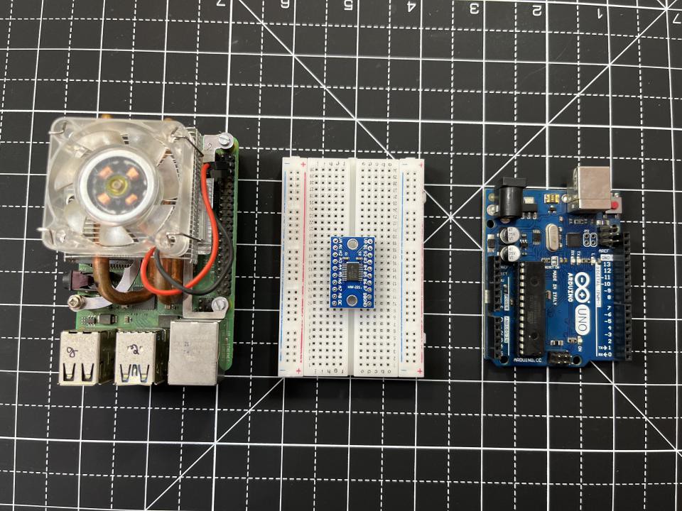
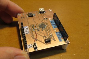
Arduino has some sensors which are made to work with 3.3volt logic. And that’s a big problem for the Arduino UNO microcontroller. Interfacing is not possible between these sensor and other microcontrollers like raspberry pi and Arduino. It is not only about 3.3 and 5volt you can design any logic with the same circuit. Usually MOSFET are used for switching between different logic levels. Either you can use IC based logic level convertors which has internal 8 MOSFET lineup to control 8-bits parallel. You can make one using PCBWAY Prototyping service. Just $5p for 10pcs of two layers of PCB boards.
Problem with the Logic levels:
If your serial sensor works on a 3.3volts like Lora devices. Then for the Arduino connection either we have to use a voltage divider network for the serial data and clock or the dedicated logic level convertor.
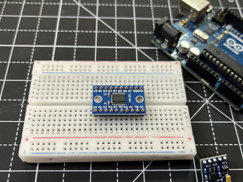
TXS0108E:
TXS0108E High-Speed Full-Duplex 8 Channel Logic Level Converter. If you’ve ever tried to connect a 3.3V device to a 5V system, you know what a challenge it can be. This bi-directional logic level converter is a small device to convert the 1.8V 3.3V 5V logic level mutually enable you to successfully set your high and low voltages and step up and down between them safely on the same channel.
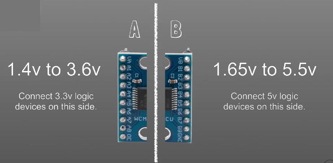
Each level converter has the capability of converting 8 pins on the high side to 8 pins on the low side. The level converter provides the serial interface compatible with UART/IIC/SPI port is very easy to use. This 8-bit non-inverting translator uses two separate configurable power-supply rails. The A port tracks the VCCA pin supply voltage. The VCCA pin accepts any supply voltage between 1.2 V and 3.6 V. The B port tracks the VCCB pin supply voltage.
The VCCB pin accepts any supply voltage between 1.65 V and 5.5 V. Two input supply pins allow for low Voltage bidirectional translation between any of the 1.2 V, 1.8 V, 2.5 V, 3.3 V, and 5 V voltage nodes.
Features:
VCCA Voltage level: 1.2V-3.6V
VCCB Voltage level: 1.65V-5.5V
It can provide 3.3-5V, 1.8-3.3V level conversion
8-bit bi-directional 3.3V-5V/5V-3.3V logic level converter board
Serial communication interface compatible with UART/IIC/SPI port easily to connect
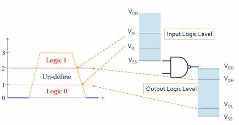
How a logic level convertor works:
In no signal condition both the input and output levels are at high logic but on different voltages (3.3 and 5volts). In this none of the Mosfet is conducting and we got a pull up this state is known as Standby.
The second state is when the 3.3V device pull the bus down to logic LOW level. The gate of the MOSFET is still at 3.3V but the source becomes low. As a result, the VGS becomes 3.3V, which is greater than the threshold voltage of the MOSFET and this allows the MOSFET to conduct.
In the third state, the 5V device pulls the high voltage side bus to logic LOW level. Through the Drain – Substrate diode, the low voltage side is pulled down until the VGS reaches the threshold voltage. The MOSFET now starts conducting which will further pull the low voltage side bus to logic LOW voltage level by the 5V device. Even in this case, both sides of the bus are at logic LOW level at same voltage.
PCBway Projects and more:
I am using PCBWAY prototype service for a long time, PCBWAY is China based PCB manufacturer deals in PCBA, SMT assembly, Stencil, Metal CNC, Flex PCB, 3-printing services and more. Sign-up to PCBWAY using this link and get free new user coupons.
Other designs of Logic level convertors:
Many module manufacturers are combining 4 such MOSFET based level shifting circuits to develop a 4- bus or 4-channel Logic...
Read more »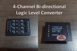
 kodera2t
 RoGeorge
 Electroniclovers123