Hulk
HulkIntro
In my hand is a 4-Digit 7-Segment display module.
The heart of this module is an inexpensive Serial LED Driver from Titan Micro Electronics called the TM1637.
In this tutorial, I am going to show you guys how to control the TM1637 4-Digit 7-Segment displays using an Arduino. If you want to displays sensor data, temperature and humidity, or want to design a clock, timer or counter, you will need this 4-Digit Seven-Segment Display.
Topics Covered

- The Basics of a 7-Segment Display
- Hardware Overview and Pinout of The TM1637 Module
- TM1637 Library Installation
- Interfacing TM1637 Module with an Arduino
- Loading The Basic Arduino Code (that comes with the TM1637 library)
- Example 1: Displaying String and a Number
- Example 2: Displaying Scrolling and Blinking Text
- Example 3: Creating a 4 Digit Counter
- Example 4: Displaying Temperature & Humidity using DHT11/DHT22
- Example 5: Creating an Arduino Based Digital Clock
And finally we will have a look at some common errors.
7-Segment Display Basics

A 7-Segment Displays consists of 7 LEDs making the shape of decimal number 8. These LEDs are called segments, because when they light up, each segments contributes in the formation of part of a decimal or hex digit.
These individual segments are labeled from ‘a’ to ‘g’ representing each individual LED. By setting a particular segment HIGH or LOW, a desired character pattern can be generated.
Hardware Overview and Pinout of TM1637 Module

The module comes with 4 right angle male pin headers. I find it a bit annoying to have the pin headers on the top side of the board. However, you can always unsolder and put them at the bottom of the board.
Now lets have a look at the GPIO pins:
CLK - is the clock input pin. You can connect it to any digital pin of an Arduino.
DIO - is the Data I/O pin. This can also connect to any digital pin of an Arduino.
VCC - Connects to 3.3V to 5V power supply.
GND - is the ground pin.
CLK and DIO pins can be connected to any digital pin of an Arduino. This gives us an opportunity to hook up a lot of these modules to an Arduino, as long as each instance has a pin pair of its own. When writing the code, we just need to specify the pin pair and then just go ahead and use them in your project.
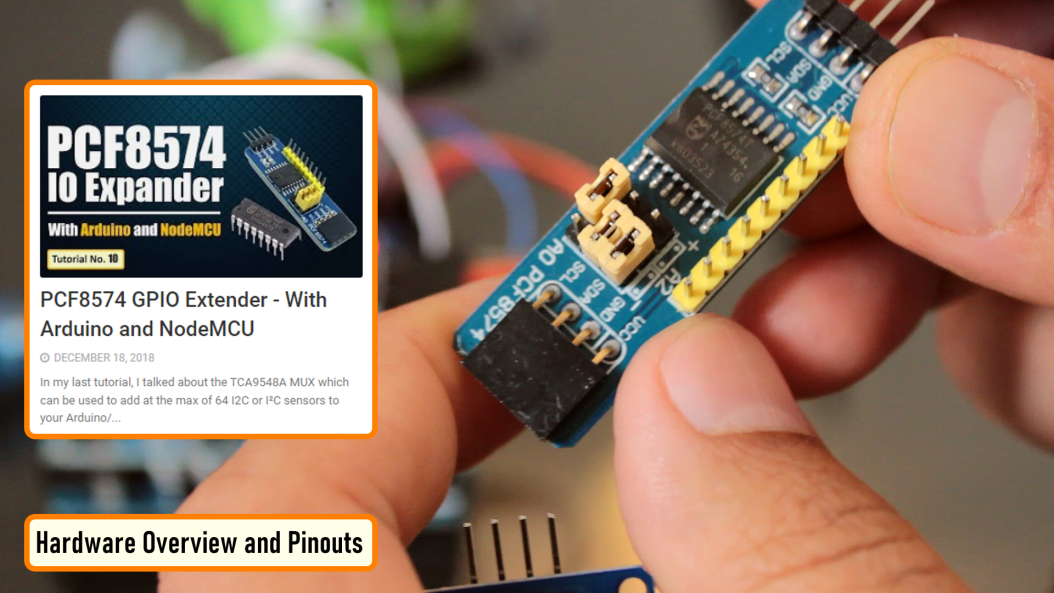
If you run out of pins on your Arduino board you can use a GPIO Pin Extenders like the PCF8574. Please check out my tutorial on the Extender module, the link is in the description below.
PCF8574 GPIO Extender: https://diyfactory007.blogspot.com/2018/12/pcf8574-gpio-extender-with-arduino-and.html
The module has 4 x 0.36 segment 7-Segment Displays and a ‘colon’ at the center for creating clock or time-based projects.
A bare four digit 7-Segment Displays usually requires 12 connection pins but the TM1637 LED Driver removes the need of the extra wiring for the 7-Segments and the entire setup can be controlled just by using 2 wires (DIO and CLK) and two more for power reducing the total wires to 4.
These modules communicate with the processor using "I2C-like protocol". The implementation is pure software emulation and doesn't make use of any special hardware (other than GPIO pins).
The module operates between 3.3v to 5v with a current consumption of 80ma and allows adjusting the brightness of the LEDs at the software level. They are available in few different colors.
TM1637 Library Installation

There are many libraries available for the TM1637 module. For this tutorial, we are going to use the "TM1637Display Library" written by "Avishay Orpaz". You can download the library using the library manager or from Github, the link is in the description below.
To install the library using "Library Manager", navigate to Sketch > Include Library > Manage Libraries…
Search for "TM1637" and look for the one by "Avishay Orpaz". Hit the "Install" button...