 Ken Yap
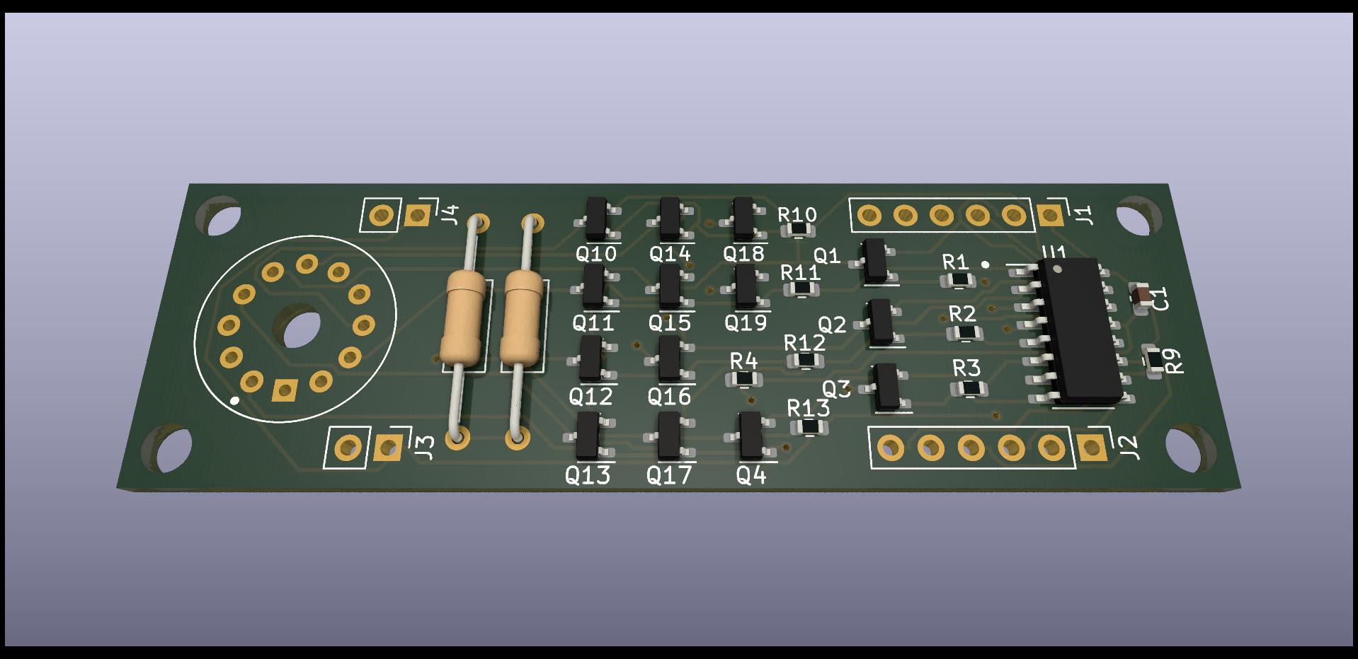
Problem
Design an inexpensive circuit using easily available components to drive nixies. Modularity i.e. same circuit for each nixie desirable so that the number of digits can be flexible.
Previous solutions
Use the TTL 74141 IC or Soviet clones. This is a BCD to 1 of 10 line nixie driver. The problem is that these chips are getting harder to find all the time.
Use a BCD to 1 of 10 output IC such as the CD4028 driving 10 high voltage switching transistors. This IC is available and reasonably priced, but 10 discrete transistors and base resistors are needed.
Use a cheap microcontroller again driving high voltage switching transistors. Costs are similar to the previous solution but a MCU gives more flexibility.
Using a shift register that can handle high voltage on the outputs, such as the TPIC6B595 which is a version of the 74HC595 that has open collector outputs and can hold off 50V. It can also sink far more current than a nixie will need. Note that when switching a nixie, you don't need to hold off the full supply voltage, only the difference between the strike and sustain voltages. One problem is that the shift register handles 8 lines so 1¼ ICs are needed, which means the design won't be modular without wasting ICs.
Other specialised ICs I have seen in searches but which might be hard to get and become unobtainium at any time.
Schematic
Here is the circuit I developed.
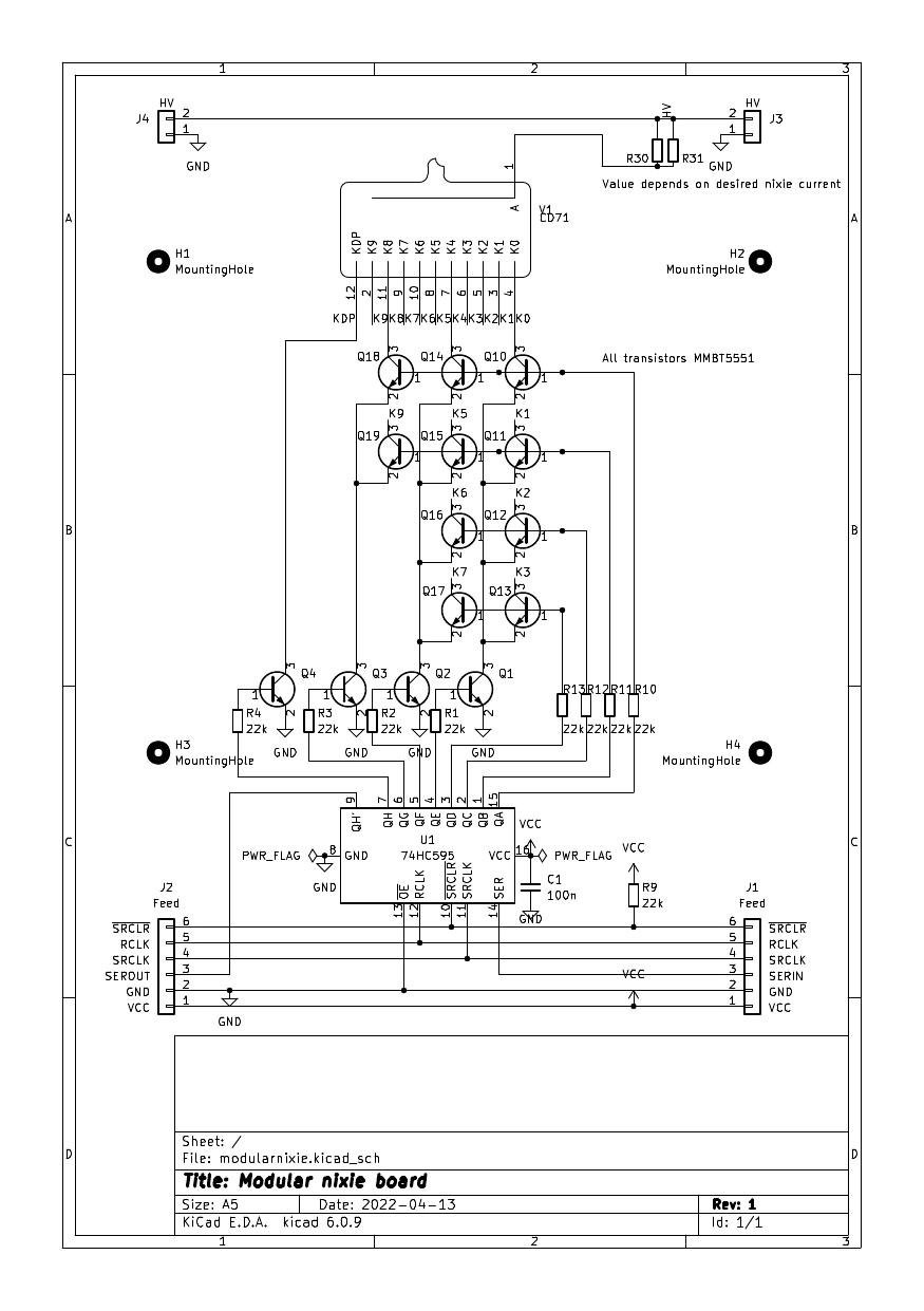
The Ircon repurposing project #Repurposing an old nixie thermometer showed how to stack two levels of transistors so that less than 10 lines are needed to turn on a cathode. This was explained in the Don Lancaster RTL Cookbook, and partly in an online article on driving nixies with transistors. With 8 lines we can use a 4x4 matrix to drive up to 16 outputs. A 3x4 matrix for 12 outputs suffices. We use the 8th bit to drive the decimal point not catered for in the previous solutions and which has to be independent.
This requires more transistors than 1 of 10 decoders = more components and soldering. But what if the transistors are in SMD packages assembled by automation? They could be very cheap. Investigation showed that JLCPCB/LCSC offers the MMBT5551 NPN transistor with 160V breakdown voltage, far more than needed, in SOT-23 form factor for about a cent each. The base current limiting resistor is also SMD. They are driven by the widely available 74HC595 shift register in a SMD package. The board is modular and cascadable to any reasonable number of digits. The time to shift in the digits is negligible compared to the display refresh period and the output is latched with a single strobe signal. The nixies are statically driven, no multiplexing, which is problematic for nixies and low duty cycles.
We will need different board layouts for nixies with a different pinout or size. But this is true whichever driver solution is adopted. This means that if you have different nixies from mine, which are the Hitachi CD71, you need to adapt the board.
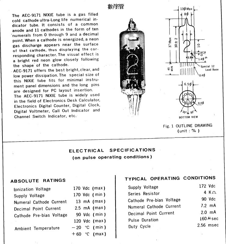
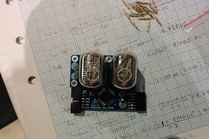
Digression: Actually the nixies I have are labelled AEC-9171 and were sold in the early 70s. No information about this model can be found on the Internet, which is not surprising as this was before the Internet. Here is an extract from the 2-page datasheet from the supplier which I have kept with the nixies all those decades. From a comparison of that and datasheets online, I concluded it was a rebranded Hitachi CD71 as the pinouts and dimensions match. Testing the nixies with a harness confirmed it, and that the nixies are still functional. The information in my datasheet isn't very useful as they are specified for multiplexing so I have gone with the CD71 data.
A special "font" is needed to drive a nixie from 8 bits of data, but a MCU takes this in its stride.
Two anode resistors in parallel are used to spread the heat dissipation. I intend to use a 12V to 170-200V boost converter for the anode supply. The HV rail is designed to daisy-chain too, like the LV rail, data,...
Read more »

 Johnny
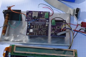
 Bharbour

 Muth
Muth
Looks good!