 guilldeas
After disassembling the device a visual inspection of both components and traces was conducted, however there were no evident signs of failure (i.e. scorching marks on the PCB, bloated capacitors, charred resistors, etc).
Because the machine wouldn't turn on the first thing to be more properly examined was the power supply. The machine could be powered either by an external standard 5V AC/DC converter or a set of AA batteries, selecting which to connect to the 5V rail by switching an SPDT. After corroborating the external PSU was in working condition the internal power schematic was traced [Fig. 1]
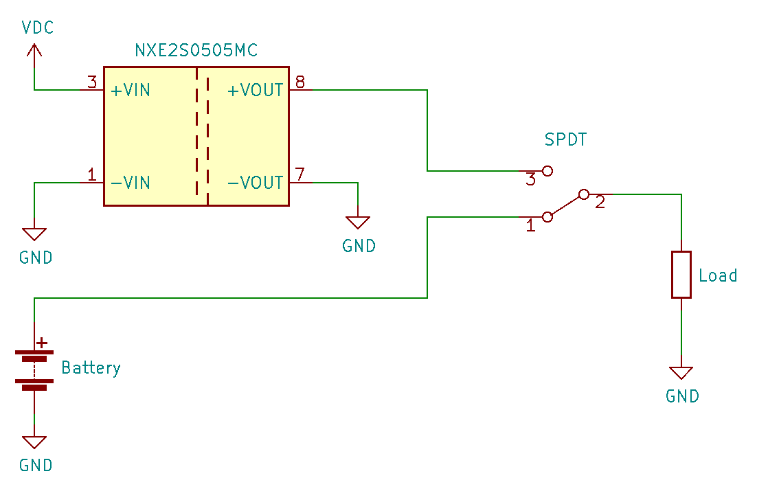
Fig. 1: Simplified internal power schematic.
The external power input was examined which was composed of a MicroUSB connector immediately followed by a DC to DC switching converter [Fig. 2], which was found to be rated for a 5V nominal input voltage and 5V nominal output.
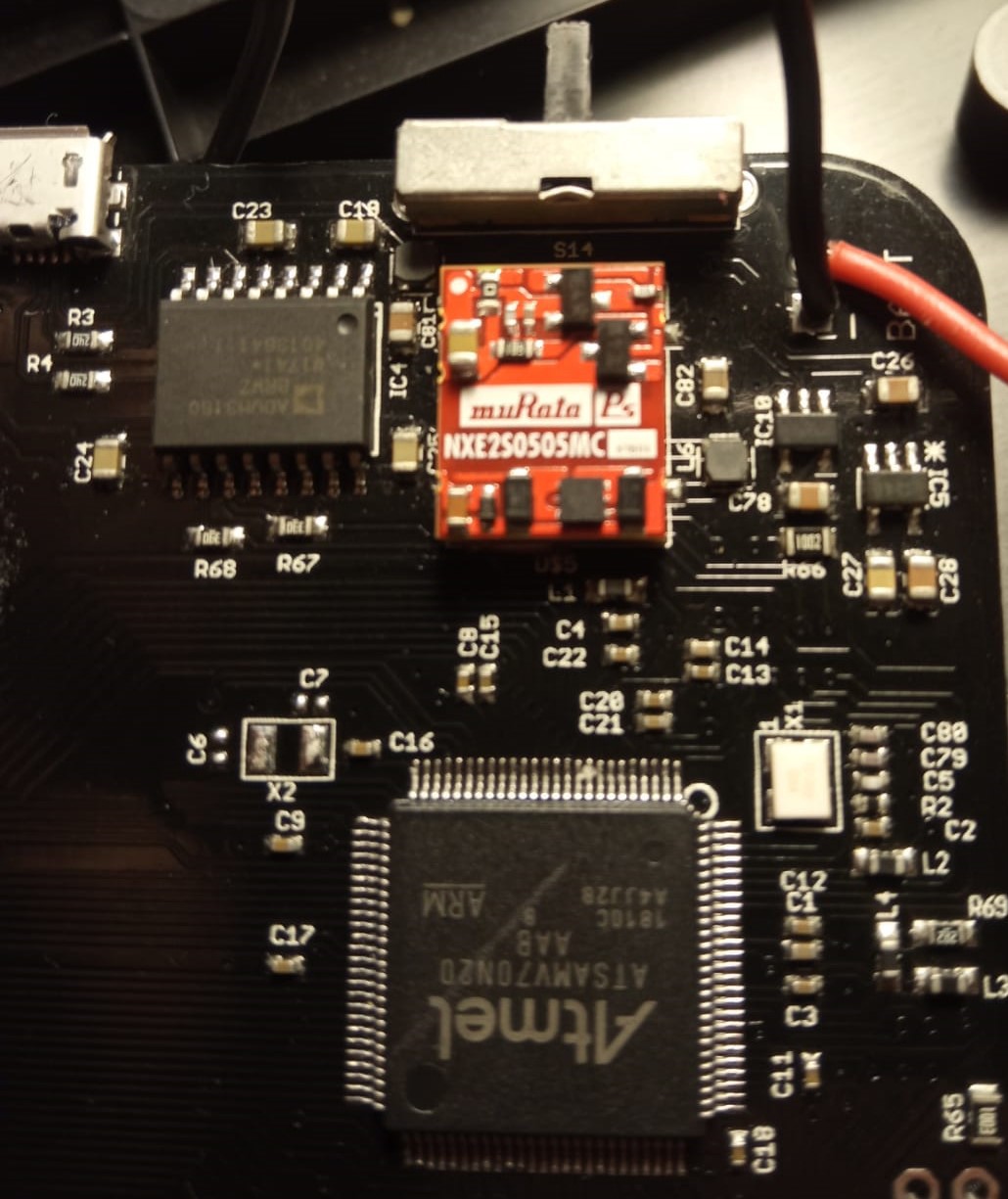
Fig. 2: DC to DC converter NXE2S0505MC.
The converter voltages were first measured with the component isolated from the load (as shown in Fig. 1). Both levels read out healthy values, however with the converter tied to the load the voltage dropped well below minimal nominal values [Table 1].
| Voltage | Isolated from load [V] | Tied to load [V] | Min. [V] |
| +VIN | 4.83 | 4.82 | 4.5 |
| +VOUT | 6.22 | 3.31 | 4.5 |
Table 1: Measured values on converter.
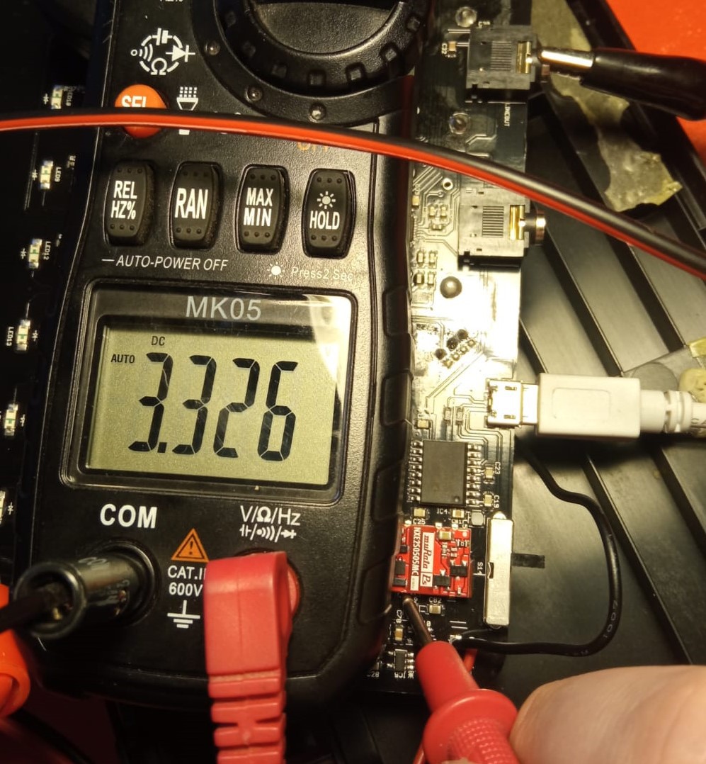
Fig. 3: Dropping 5v supply rail at converter output.
This could indicate the converter was demanded too much current from a short further down the line, thus dropping the 5V rail to a point where the microcontroller [Fig. 2] could not switch on.
To prove this wasn't instead a problem with the converter being faulty the following test was performed. A regulated DC power supply was connected to the battery terminals thus powering the synthesizer while bypassing the converter. The power supply's voltage was set to the equivalent of the synthesizer's 3 AA batteries in series (4.5 V). The supply was then current limited to the synthesizer maximum current draw. Nonetheless this information was not stated on the owners manual so the maximum current drawn was estimated to be the maximum current delivered by the DC/DC converter. According to the NXE2 datasheet the maximum power delivered is 2W, which means the maximum current at 5V is:
Thus it was assumed a healthy converter would be expected to supply at maximum 400 mA without dropping it's output voltage. The DC power supply was then set to 4.5V and current limited to 400 mA. Upon powering the synthesizer from the external power supply the over current protection was immediately tripped which proved the problem was indeed a short and not the converter.
To find a shorted component without visual cues the device was run for a while (current limited by the regulated DC supply to avoid further damage). This allowed the failing component to heat up to a point that it could be identified by touch. This component was found to be IC11 [Fig. 4], an audio codec (SGTL5000).
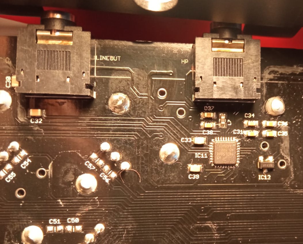
Fig. 4: Overheating audio codec (IC11) and both output jacks LINEOUT and HP.
This component implements various functions like switching inputs into outputs, equalizing the audio signal and driving both the headphones and line outputs.
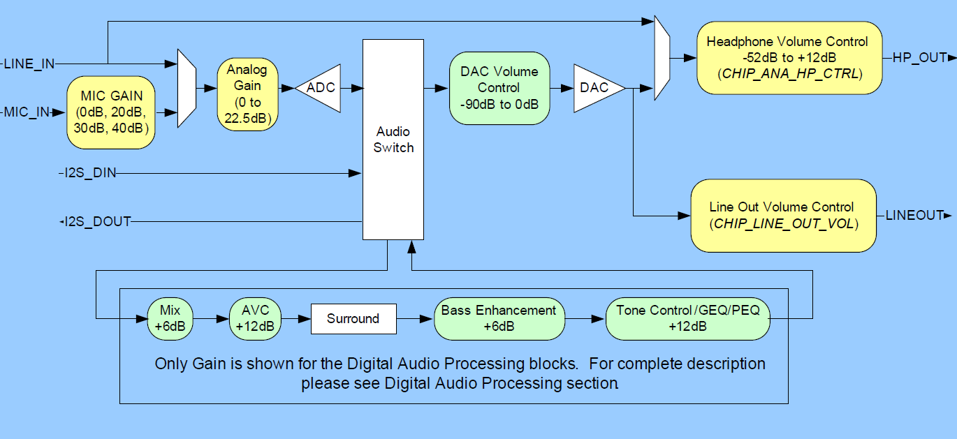
Fig. 5: SGTL5000 block diagram.
To find the fault all of the pins were tested for shorts with ground, it was found that the output resistance of the right channel [Fig. 7] line output was anomalously low compared to the left channel [Fig. 6].
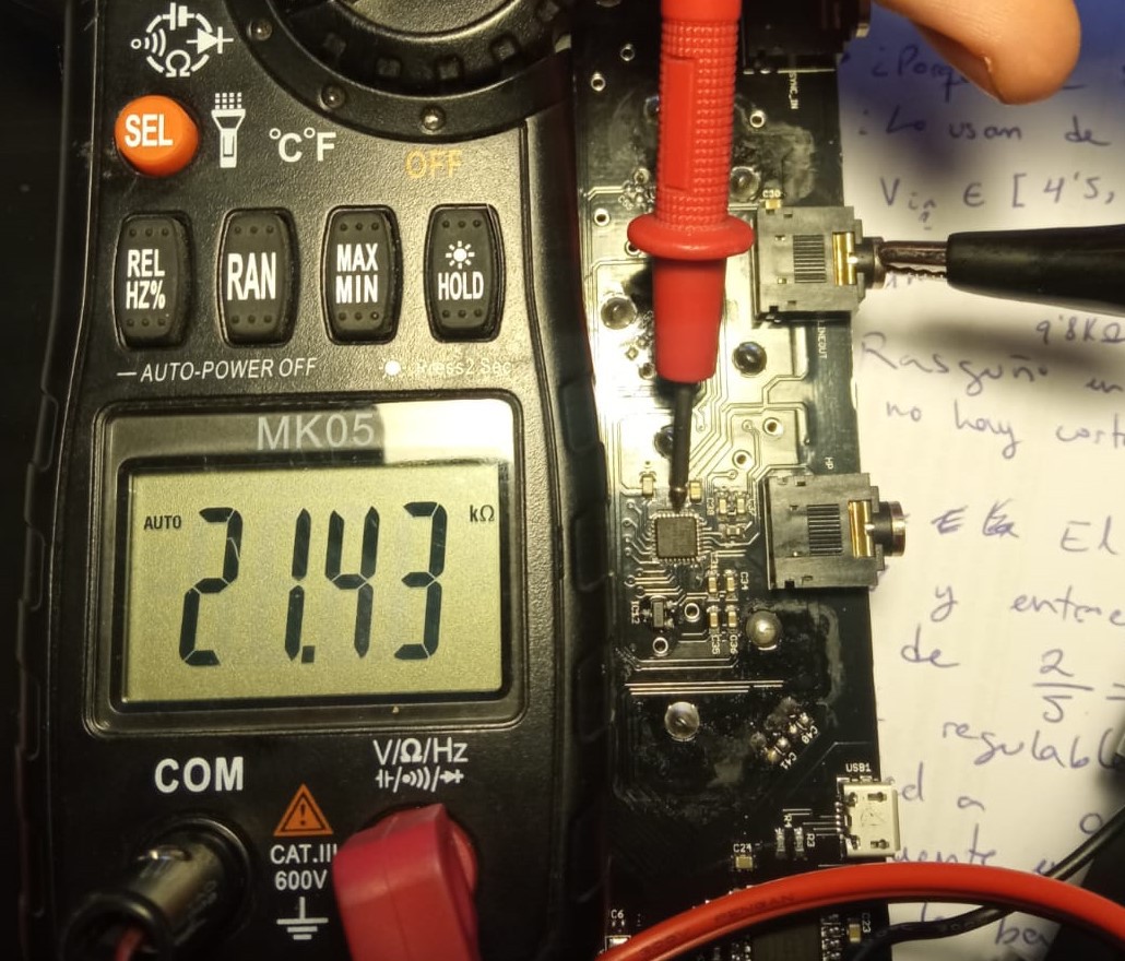
Fig. 6: Left line output shows 21.3 KΩ to ground.
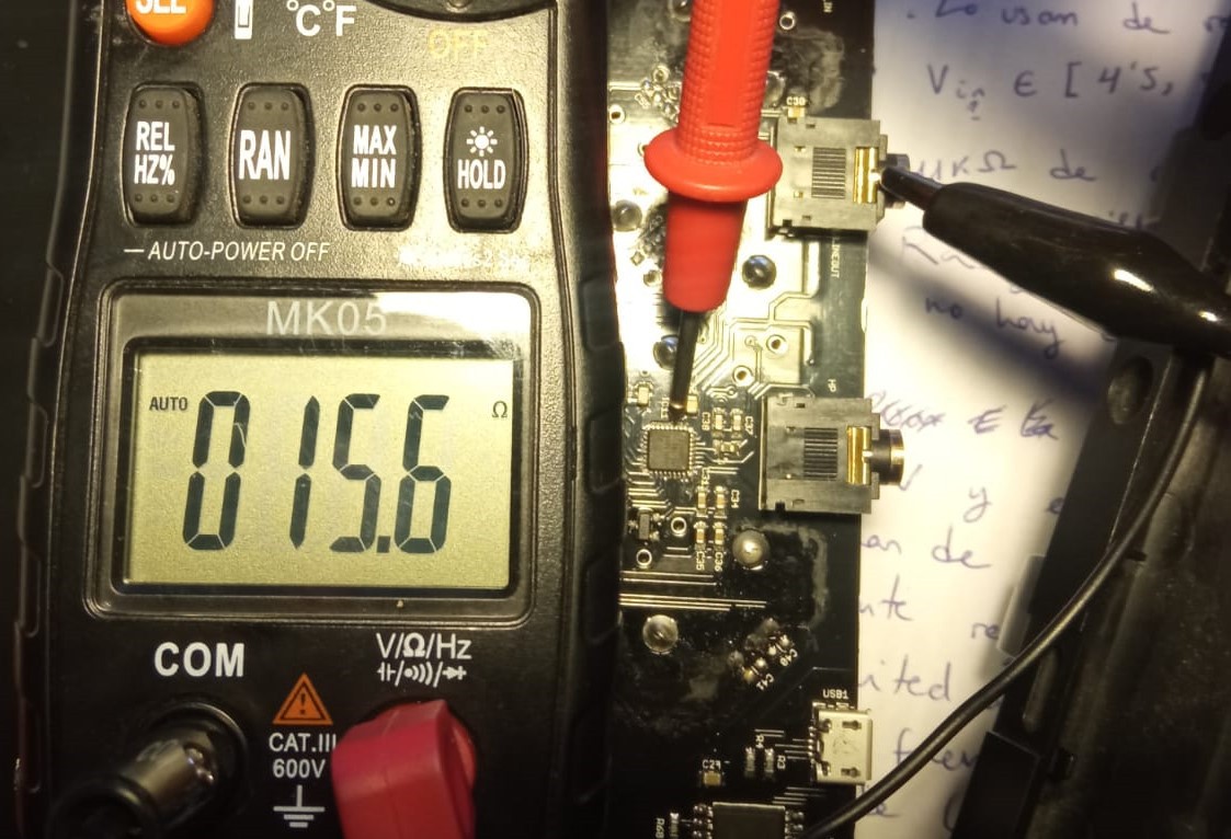
Fig. 7: Right line output shows 15.6 Ω to ground.
This was determined to be a short inside the IC since the rest of the circuit is decoupled from the input by a capacitor (C9 in Fig. 8, C32 in Fig. 4)
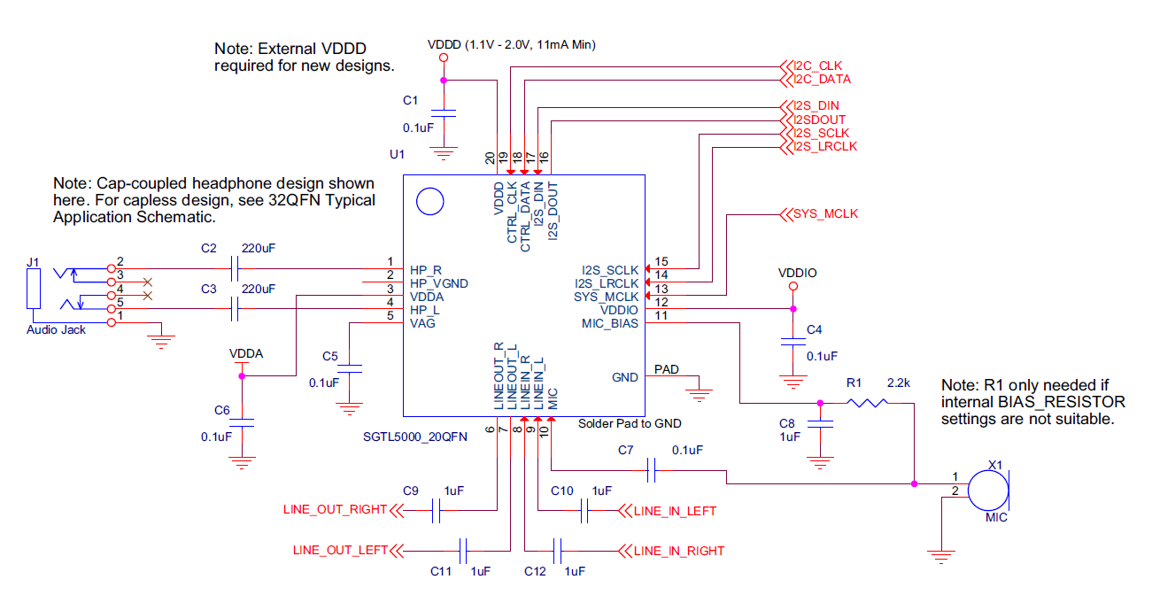
Fig. 7: SGTL5000 proposed design followed in the PCB.
Finally the fault has been identified as a short to ground inside the audio Codecs die, however this is an IC the device cannot operate without, the music produced inside the device can only be recorded or listened to through this chip. Two options are left then, bypassing it or replacing it.
Bypassing the chip is not feasible since the output is analog and the analog inputs (LINE IN and MIC IN in Fig. 5) are left disconnected in the PCB, this means the audio must be fed into the IC through the only other input connected, (I2S_DIN in Fig. 5) that input happens to be a digital signal with an I2S protocol, since the output is analog and the input must be digital the internal ADC of the IC is unavoidable and a direct bypass cannot be performed.
Replacing the IC could be feasible since it most likely doesn't store any obscure firmware written during production, it has a basic system of registers that are probably read and written by the microcontroller whenever the device is switched on. However the footprint for the IC can only fit a QFN package [Fig. 8] which requires micro soldering techniques due to it's minute size and pad pitch as well as the use of a hot air soldering station due to it's ground pad and pins hidden below the package. This is something that is currently outside my scope so neither bypassing, nor replacing the IC are an option for me at the moment, the project was thus documented and shelved for future attempts.
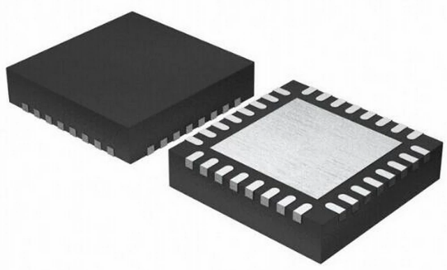
Fig. 7: 32 QFN package used for the SGTL5000.
Discussions
Become a Hackaday.io Member
Create an account to leave a comment. Already have an account? Log In.