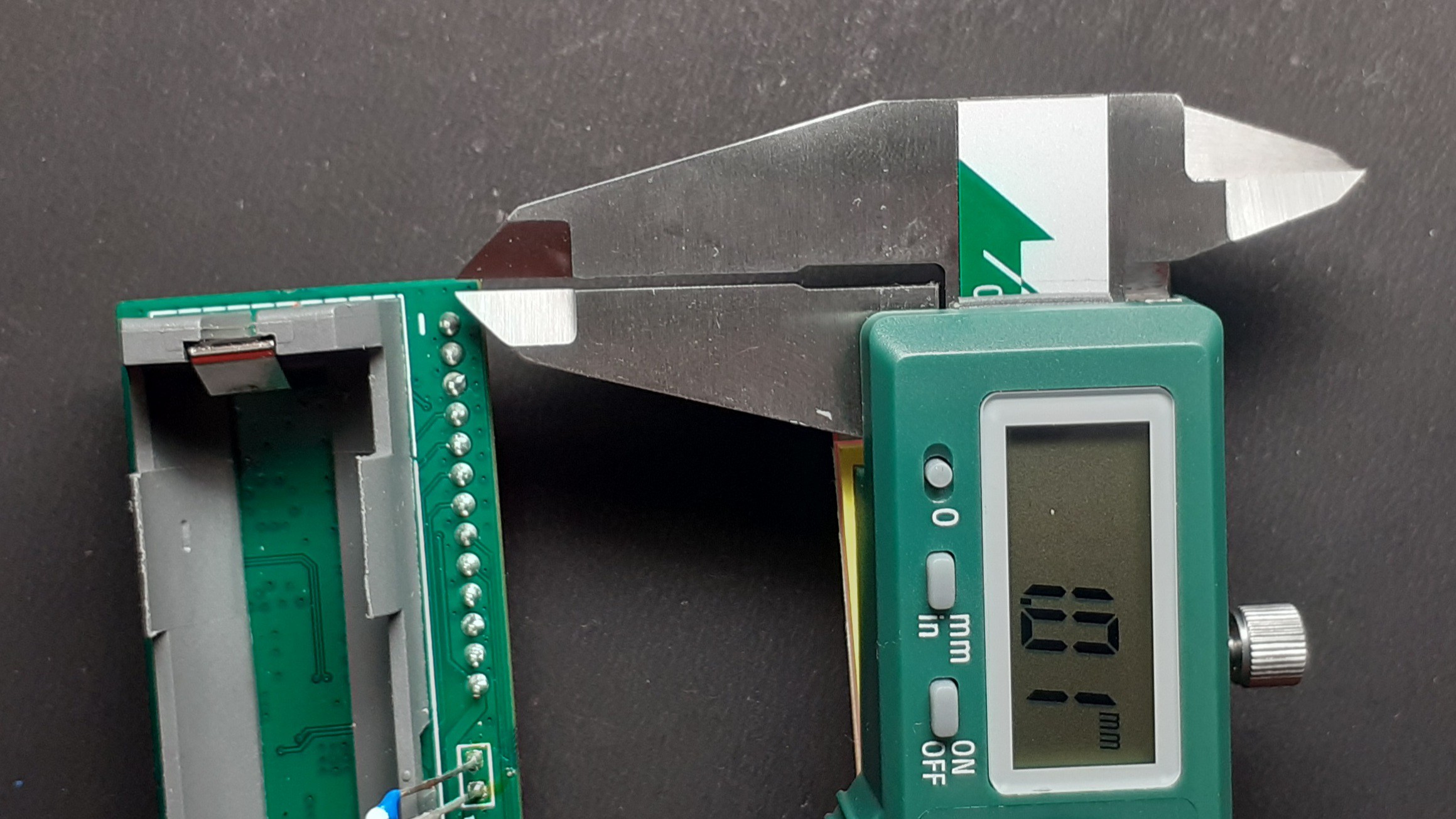
Close
0%
0%

Open UpCell

An open source, USB Type C PD, single-cell BMS for Lithium batteries

Public Chat
Similar projects worth following
Open UpCell is a USB Type-C PD single cell lithium-ion battery management system with either 5 v or 3.3 v outputs, up to 14 v input, and an i2c interface for battery and charge status monitoring. You can check battery fuel gauge, charge status, charge voltage selection, charge current selection, and more via the provided Arduino IDE and PlatformIO SDKs. Output and i2c voltage is selectable between 3.3 v and 5 v, and the board comes with Seeed Groove (JST-PH) and Stemma QT (JST-SH) 4 pin connectors to enable plug and play operation with pre-existing projects. Open UpCell is also capable of being a simple, rudimentary inverter for a project, with an up to 15 W output (5 v, 3 A) - enough to power a Raspberry Pi Board or small router.

Open UpCell enables rapid prototyping of battery-dependent projects while keeping things simple from setup to charging. It can be used to power existing Seeed Grove module chains and Adafruit Stemma QT module chains. It can also keep your projects powered and usable off the grid, perfect for some IoT and Edge projects, like an IoT soil sensor cluster or a simple PIR motion detector. And, at just a few mm larger than a standard 18650 battery, this useful system is small enough to be concealed in a DIY wearable project.

Features & Specifications

  • Safety: Short circuit protection, temperature loop control, input over-voltage protection, input over current protection, overcharge protection, fused input
  • 3.3 v and 5 v output options
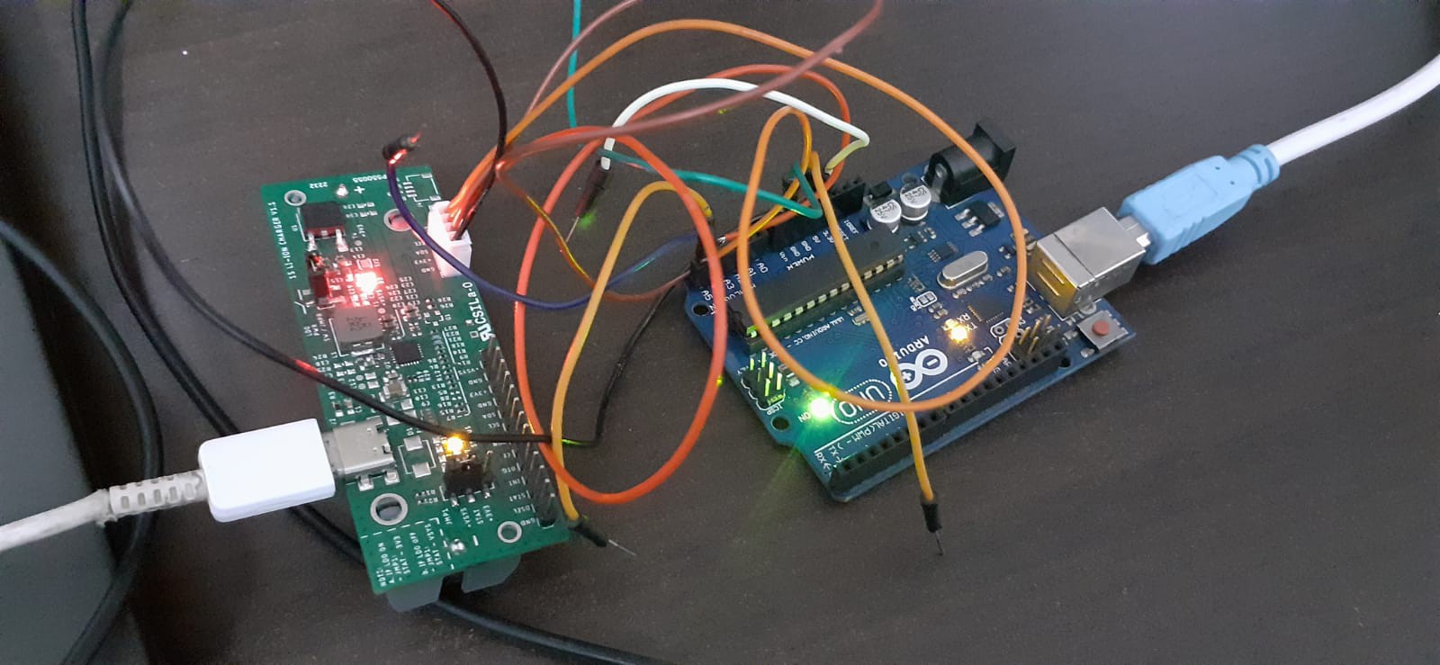
  • STEMMA QT and Seeed Groove connectors for plug and play
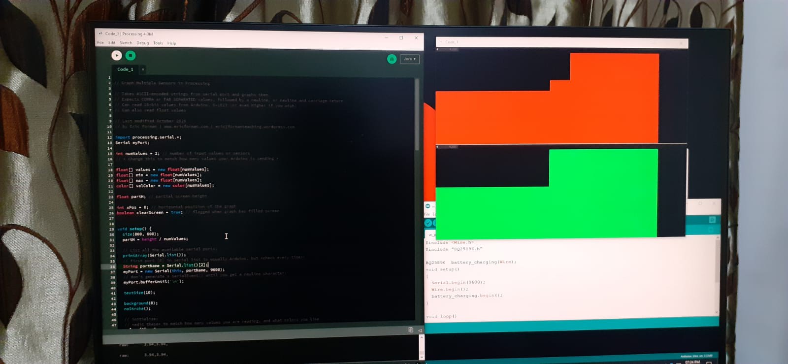
  • Battery gauge over i2c
  • Charge control, status, and monitoring over i2c (1.8 v, 3.3 v, and 5 v compliant i2c)
  • Arduino IDE SDK for i2c communication
  • 5 v, 9 v, 12 v USB PD and Fast Charge capable (Up to 14 v or 3 A)
  • Compatible with any capacity of Li-Po or 18650 cells, 21600 cell, or equivalent lithium chemistry cell (must be single cell)

  • 1 × BQ25895 1S I2C Battery Charging IC
  • 1 × PPTC fuse 3.8A 12V
  • 1 × 18650 Li-Ion Non-Polarized Cell Holder
  • 1 × NTC 10K
  • 1 × LDO 3.3V 1A

  • Update 13: Powering up the Raspberry Pi using Open Upcell

    Padmalaya Rawal05/10/2023 at 12:00 0 comments

    You: Can we power up the Raspberry pi using Open Upcell?

    We: Absolutely yes

    You: How?

    We: Here are the different methods you can use to power up the Raspberry pi:

    To power up the raspberry pi we generally have 2 methods viz., 

    1.  Using GPIO

    2. Using USB power supply

    To power up your projects using Open Upcell, you have also 4 options viz.,

    1. Using Male header

    2. Using Seeed Groove (JST-PH) 4 pin connector

    3. Using Stemma QT (JST-SH) 4 pin connector

    4. 2 pin solder pad

    So, the total number of combinations we have are as follow:

    S. No.Open Upcell connectorRaspberry pi connector
    1Using Male headerUsing GPIO
    2Using Male headerUsing USB power supply
    3Using Seeed Groove (JST-PH) 4 pin connectorUsing GPIO
    4Using Seeed Groove (JST-PH) 4 pin connectorUsing USB power supply
    5Using Stemma QT (JST-SH) 4 pin connectorUsing GPIO
    6Using Stemma QT (JST-SH) 4 pin connectorUsing USB power supply
    72 pin solder padUsing GPIO
    82 pin solder padUsing USB power supply

    Before we go further, let's see the GPIO Pins from where we will be powering up the Raspberry pi. Please note that for this tutorial we are using Raspberry pi 3 Model B. Before powering any other please make sure that you are connecting the power to the correct pins, else you may damage you Raspberry pi permanently.


    CAUTION: Please make sure that you are supplying power to the correct GPIO Pins, else you may end up damaging you Raspberry pi permanently. 

    Here is the GPIO pinout for Raspberry pi 3 Model B, we will use GPIO Pin 4 and 6.

    You: Out of all 8 possible combination, which ones we are going to use? ALL? 

    We: Nope, we don't need to try all the 8 combinations

    You: Why?

    We: Because internally all the VCC pins and GND pins are connected to same pin of BQ25895 IC (brain of the board) which is PMID pin and GND pin. PMID pin is pin no. 23 and GND pin is pin no. 17 or 18 as per the IC pinout from the datasheet.

    Before we continue further we expect that you have enough knowledge on how to do the initial setup for raspberry pi and have already completed that. Please connect all the peripherals such as mouse, keyboard, HDMI cable & LAN cable(optional) and if you have set it up over SSH, you are already good to go. 

    Method 1:

    From the table mentioned above we will be connecting male header (PMID & GND) of the open Upcell to the pin 2 or 4 and 6 of the raspberry pi respectively. And here is how the setup looks.

    You can see the below image for the PMID pin and GND pin, pins are also indicated on the board itself as well but are little offset due to space constraints.

    We booted up the Raspberry pi and boom🎆, we got a Low voltage warning as shown below

    To find the culprit, I have attached the multimeter to know whether it's really a low voltage or it's a false warning because after searching a lot on the internet we found that people are getting this low voltage warning even after using a good quality and power rating adapters.


    Method 2: 

    We find that it's actually the low voltage. Before we find out the reason, let's test the next combination which is using male header of Open Upcell to power up the raspberry pi over USB, for that we have made a custom connector on which one side is female USB connector and on the other side we have 2 pin male header to connect it on the breadboard. And this time we have kept the multimeter attached.

    And this time again we are getting low voltage on the multimeter. But the question is why are we getting the low voltage? Wait for a while we will share the reason too. 


    Method 3:

    In this method we will be using a Seed studio's (JST-PH) 4 pin connector of Open Upcell and will power the Raspberry pi using GPIO pin 2 or 4 and GPI0 Pin 6. Please make sure that you are connecting the correct corresponding wire of JSP-PH connector to Raspberry pi VCC pin and GND pin. For your reference we have also mentioned the VCC pin and GND pin on the silk layer as well which can be seen in the image below:

    After connecting...

    Read more »

  • Update 13: Data-sheet V/S Real life Testing

    Padmalaya Rawal01/27/2023 at 13:20 0 comments

    Hey Tinkerers, 

    We are actively testing all the features of Open Upcell and comparing the result against the expected result of Datasheet as well. Here is the Battery Voltage profile from Datasheet and the one we have tested in real-life. We have used Influx for recording and analysing the results.

    Datasheet:

    Real life:


    Our Crowd Supply campaign will be live very soon, SUBSCRIBE the mailing list on Crowd Supply so that you won't miss any update :)
    Crowd Supply Page: https://www.crowdsupply.com/sikra/open-upcell

    Happy Tinkering :)

  • UPDATE 12: Performance Test

    Padmalaya Rawal01/25/2023 at 14:42 0 comments

    Hey Creators,
    For last few days we were working on the integration of Open Upcell with InfluxDB IoT platfoem for easy analysis of performance of battery and we have prepared different graphs using parameters such as Input Voltage, battery voltage, charging voltage, charging current, NTC temperature, Environment temperature, etc. Here is one of those graphs.


    We have used ESP32 board and DHT11 temperature and humidity sensor for the same. The code for this is

    //New code with env temp
    
    #include <WiFiMulti.h>
    #include <InfluxDbClient.h>
    #include <InfluxDbCloud.h>
    #include <Wire.h>
    #include "BQ25896.h"
    #include <Adafruit_Sensor.h>
    #include <DHT.h>
    #include <DHT_U.h>
    
    #define DHTPIN 2     // Digital pin connected to the DHT sensor 
    #define DHTTYPE    DHT11     // DHT 11
    DHT_Unified dht(DHTPIN, DHTTYPE);
    
    uint32_t delayMS;
    BQ25896  battery_charging(Wire);
    WiFiMulti wifiMulti;
    
    #define DEVICE "ESP32"
    #define WIFI_SSID "EB LAB"
    #define WIFI_PASSWORD "EB13579@#$fhj5"
    #define INFLUXDB_URL "https://europe-west1-1.gcp.cloud2.influxdata.com"
    #define INFLUXDB_TOKEN "uSG2NN90KiFyXjyOjuO5rJHIp01q3-oBk9A8b7VCwC0iTsiJroAmixPwHZKrcDqOjBHNOracI_dMBFBfrAFu7g=="
    #define INFLUXDB_ORG "6039c76badddc47c"
    #define INFLUXDB_BUCKET "Open Upcell performance test"
    
    // Set timezone string according to https://www.gnu.org/software/libc/manual/html_node/TZ-Variable.html
    #define TZ_INFO "UTC5.5"
    
    // InfluxDB client instance with preconfigured InfluxCloud certificate
    InfluxDBClient client(INFLUXDB_URL, INFLUXDB_ORG, INFLUXDB_BUCKET, INFLUXDB_TOKEN, InfluxDbCloud2CACert);
    
    // Data point
    Point sensor("ENV Temp");
    Point sensor1("NTC Temp");
    Point sensor2("Input Voltage");
    Point sensor3("Charging Voltage");
    Point sensor4("Battery Voltage");
    Point sensor5("Charging Current");
    
    int rate =100;  //Sampling rate
    bool label= true;
    bool influx_charge_status=true;
    
    void setup() {
      Serial.begin(115200);
      dht.begin();
      Wire.begin();
      battery_charging.begin();
      WiFi.mode(WIFI_STA);
      wifiMulti.addAP(WIFI_SSID, WIFI_PASSWORD);
      Serial.print("Connecting to wifi");
      while (wifiMulti.run() != WL_CONNECTED) {
        Serial.print(".");
        delay(500);
      }
      Serial.println();
    
      // Add tags
      //sensor.addTag("device", DEVICE);
      //sensor.addTag("SSID", WiFi.SSID());
      
      timeSync(TZ_INFO, "pool.ntp.org", "time.nis.gov");
      
      if (client.validateConnection()) {
        Serial.print("Connected to InfluxDB: ");
        Serial.println(client.getServerUrl());
      } else {
        Serial.print("InfluxDB connection failed: ");
        Serial.println(client.getLastErrorMessage());
      }
    }
    
    void loop() {
    
        battery_charging.properties();
      
        BQ25896::CHG_STAT status = battery_charging.getCHG_STATUS();
    
        //To keep the influx_charge_status true when the charge status is either of these three: Not charging, pre charge or fast charge
        if ((status == BQ25896::CHG_STAT::NOT_CHARGING)||(status == BQ25896::CHG_STAT::PRE_CHARGE)||(status == BQ25896::CHG_STAT::FAST_CHARGE)){ 
            influx_charge_status= true;
        }
    
        //If the charge status is charged, it will make the influx_charge_status = false and stop sending the values
        else {
            influx_charge_status=false;
        }
    
       if (influx_charge_status==true){ 
        sensors_event_t event;
        dht.temperature().getEvent(&event);
        
        sensor.clearFields();
        sensor1.clearFields();
        sensor2.clearFields();
        sensor3.clearFields();
        sensor4.clearFields();
        sensor5.clearFields();
          
        sensor.addField("Env Temp",event.temperature);
        sensor1.addField("NTC Temp",battery_charging.getTemperature());
        sensor2.addField("Input Voltage",battery_charging.getVBUS());
        sensor3.addField("Charging Voltage",battery_charging.getVSYS());
        sensor4.addField("Battery Voltage",battery_charging.getVBAT());
        sensor5.addField("Charging Current",battery_charging.getICHG());
      
        Serial.print("Writing: ");
        Serial.println(client.pointToLineProtocol(sensor));
        Serial.println(client.pointToLineProtocol(sensor1));
        Serial.println(client.pointToLineProtocol(sensor2));
        Serial.println(client.pointToLineProtocol(sensor3));
        Serial.println(client.pointToLineProtocol(sensor4));
     Serial.println(client.pointToLineProtocol(sensor5));
    ...
    Read more »

  • UPDATE 11: OSHWA certified✅

    Padmalaya Rawal01/19/2023 at 07:29 0 comments

    Hey Supporter,

    We are excited to share that our project is now Certified open source project. We have received the certification from OSHWA with OSHWA UID US002163 . You can check out the open source files on github page (https://github.com/sikra-io/open-lithium-bms/tree/v1.4 ). We are still updating the documentation and files. The CAD files are still not updated on github, we are still finalizing the design so that you can use it without any problem.
    OSHWA certification page: https://certification.oshwa.org/us002163.html

    We are getting closer to the launch date for Open Upcell on Crowd Supply, if you haven't checked it out yet. Please have a look at it and consider subscribing for updates so that you don't miss it.

    Crowd Supply page: https://www.crowdsupply.com/sikra/open-upcell

    Keep Tinkering & supporting :)

  • UPDATE 10: Clear filament test

    Padmalaya Rawal01/18/2023 at 16:07 0 comments

    Hey Innovators,
    Back on the enclosure update, we have printed out the latest enclosure in Clear PLA PRO filament. The enclosure in clear material looks pretty cool to me and also by doing so I am able see the indicator LEDs as well.

    We are still playing with settings to print the enclosure in such a way that we will be able to see through it. What are you suggestion on this? Should we use clear material or go with the colored one? Here are a few pictures. You can checkout previous logs of enclosure in colored material for comparison.


    Also, don't forget to checkout our Crowdsupply campaign which will be live soon. Also, make to SUBSCRIBE the mailing list on crowdsupply for updates.
    Crowd Supply Page: https://www.crowdsupply.com/sikra/open-upcell

    Keep Innovating :)

  • UPDATE 9: Sneak Peak in testing

    Padmalaya Rawal01/17/2023 at 13:47 0 comments

    Hey Awesome project creators,

    At present we are working on some tests but the question is which tests? Will you be able to guess them? Let's see, here is a sneak peak for the same. We will share all the instruction once we are done with all the codes and are self-satisfied.

    Our setup for testing:

    Here are some windows that you might need to guess what we are testing 😁

    We will reveal it soon, stay tuned w/ us. And don't forget to check out and  subscribe for our crowd supply campaign : https://www.crowdsupply.com/sikra/open-upcell

    Till then , Happy making :)

  • UPDATE 8: The Clever CAD Design

    Padmalaya Rawal01/13/2023 at 09:21 0 comments

    Hey Tinkerers,

    Here comes another revision of enclosure. We have designed it in two pieces by utilising the huge 1mm space 😂 which I mentioned in one of our previous post. If you see it carefully we have used the space available on perimeter on both sides and we made it to snap fit. Sending the files for 3D printing.

    Till then, you can checkout our crowdsupply page: https://www.crowdsupply.com/sikra/open-upcell

    We would love to hear suggestion & reviews from you. Comment them below.

    Happy Tinkering :)


  • UPDATE 7: Arduino & processing code

    Padmalaya Rawal01/12/2023 at 14:03 0 comments

    Hey Creators,

    We are now actively working on Arduino as well as on processing code to plot various graphs according  to the requirement. Here is a sneak peak into the circuit, code and output. Don't worry we will present it in more readable format for you once we will complete it. Till then, do checkout our Crowd Supply campaign which will be live very soon.

    Crowd supply page: https://www.crowdsupply.com/sikra/open-upcell

    Happy creating :) 

  • UPDATE 6: The clever CAD design

    Padmalaya Rawal01/11/2023 at 07:49 0 comments

    Hey Makers,

    Our last 3D-printed part was good enough and holds our PCB so well but our goal was to build an enclosure for which we don't need any adhesive material or screws to hold the Open Upcell in place. And we just discovered a huge space around the perimeter of PCB which is 1 mm😂.

    Let's see how we will be able to use this huge space to hold the Open Upcell in place. Don't forget to check out our project campaign on Crowdsupply. You can either search "Open upcell" on Crowd Supply or use this link:https://www.crowdsupply.com/sikra/open-upcell
    Happy Tinkering  :)

    Stay tuned for more updates .............

  • UPDATE 5: 3D printed enclosure V3

    Padmalaya Rawal01/10/2023 at 12:52 0 comments

    Hey Developers,

    We are now getting close to the final version of the enclosure. Today, we have our 3D-printed V3 of the enclosure. The board fits very well in it. The only feature which is left for now is a mechanism to hold the board in place w/o any screws/tape/glue. We are already working on it, till then stay tuned.

    I hope you have already checked out our Open Upcell Project on Crowdsupply. If not, check it out by searching "Open Upcell" on crowd supply or just by clicking this link.

    Happy Hacking :)

View all 14 project logs

  • 1
    3D Printer setting & specifications

    We have used Creality's Ender 3 V2 which has a bed size of 220mm*220mm and settings for slicing software (Cura in my case are as follows) along with other  information:

    Bed Temperature: 60℃ (Room temperature is 11℃ )

    Nozzle Temperature: 205℃ 

    Support: No

    Material: Red PLA+

    Layer height: 0.2mm

    Speed: 50mm/s

    Retraction distance: 10mm

    Retraction speed: 50mm/s

    Build plate adhesion: None

    Infill: 20%

    Nozzle size: 0.4mm

    Nozzle material: Brass                 

    Time: 1hr 45 min

    Material used: 12g

    If you still need any help, let us know & don't forget to SUBSCRIBE to our Crowd Supply campaign for the Open Upcell project.               

View all instructions

Enjoy this project?

Share

Discussions

Similar Projects

Does this project spark your interest?

Become a member to follow this project and never miss any updates